Subsections of Mech Catalog
Holes


The Holes tool is used to create any type of normalized hole on the part. This dialog box is displayed every time you drop the IPROHoles tool on the part or when you edit an existing hole.

Click to show content from YouTube.
(read the service's privacy policy)
Description of the User Interface
At the top of the dialog there are the buttons useful to control the placement of the hole and a combo box used to select the Unit of Measure related to the parameter of the hole. At the left of the Unit of Measure combo there is a button that is used to display a list containing all the Holes existing on the selected part. This list is very useful if you need to modify several holes at once. Clicking on the button, the dialog box will be enlarged, and the list of holes placed on the part will be displayed. At this point, selecting the hole in the list, the fields of the dialog box will be updated in order to reflect the values of the selected hole. A very powerful functionality of this tool is that, if you select an hole placed on a different part, this list will be updated in order to contain all the holes placed in the new selected part.

Components
The family of hole can be selected using the two tabs. When you change the type of the hole, the dialog box is immediately updated.

You can change the type of hole clicking one of the four option buttons placed under the tabs. Every time you change the selection, the dialog box is updated in order to show you all the parameters related to the hole.
Settings

The buttons included in this box allow you to save the current hole settings. This allows them to be quickly recalled in future sessions. From the combo box you can select saved holes, while the button on the right allows you to open a dialog box for managing and reordering settings (which are separate for plain and threaded holes).
Parameters

Type GAS - When this button is checked, a combo boxcontaining all the normalized GAS diameters becomevisible.
Diameter - d or M - This option is used to select orto insert the required diameter for the hole. A label placed at the right of this item shows the Actual Diameter. In the case of simple hole, the Actual Diameter is the value of diameter minus the tolerance value. In the case of thread holes the Actual Diameter is the diameter minus the pitch.
- Pitch Thread Coarse/Fine - If you select a threaded hole, this combo box allows you to select the pitch type.
- Tolerance - If this option is selected, a combo box containing available tolerances will be displayed.
Hole Depth - L - This option is used to insert or select the depth of the hole. This option is disabled if you check the Through option.
- Through - If this option is selected, the hole goes through the entire part from the selected face to the opposite face.
Bottom V - a - This option is used to control thebottom shape of the hole. This option is disabled ifyou check the Through option or the Flat option. When this option is enabled you can set the bottomangle of the hole.
Taper Angle - g - This option is used to set a taperangle for the hole. To enable this item, you have tocheck the Apply option.
Hole Color - This option applies a color to the inside wall of the hole.
Chamfer End - with this option it is possible to apply a chamfer on both edges of the hole (only initial, or initial and final if it’s through)
Drill Parts - If you select this option, you can “drill” multiple parts in one operation.
In this way, you can generate holes even in the parts below the first one, up to the desired length.
If, you also enable Through opt. the Drop-down menu Drill Parts will also be visible, from here you can set the number of parts to be drilled; which will generate as many through holes in the selected parts below.
When you select a Counter Sink or Counter Bore hole, the section related to these parameters becomes visible.

The items contained in this section are used to set the diameter, the depth and/or the angle of a counter bore, counter sink or counter drill hole. Furthermore two buttons allow you to automatically load the Standard values defined for the hole.
When you select a Thread hole, the section related to thread parameters becomes visible.

The items contained in this section are used to define the Pitch of the thread, the length of the thread and the callout to set in the 2D drawing.
The data structure behind Holes
All the data files related to hole are placed in the folder ..\Norme\Holes
This is the list of the files contained in the folder and a description of their structure:
Note
The data files can edited also with the Library Data Manager application.
Diameters.dat - Diameters_ENG.dat
These files contain the list of available diameters and their associated tolerances. Any row starting with the char # is considered as a comment. The row starting with the tag Toll is used to define the label of the Tolerance available. All the values after the Toll tag, will be inserted in the Tolerance combo box.
## ============================================================================
## * IRONPROXT - PARAMETRICLIBRARY - FronemaSrl *
## ============================================================================
##
##		Bohrungsdurchmesser / Diameters for Holes
##
<Toll> H5     H6     H7     H8     H9     H10    H11    H12    H13    H14    +1mm
##Diam H5     H6     H7     H8     H9     H10    H11    H12    H13    H14    +1mm
1.6	   0.004  0.006  0.01   0.014  0.025  0.040  0.060  0.100  0.140  0.250  1
2      0.004  0.006  0.01   0.014  0.025  0.040  0.060  0.100  0.140  0.250  1
2.5    0.004  0.006  0.01   0.014  0.025  0.040  0.060  0.100  0.140  0.250  1
3      0.005  0.008  0.012  0.018  0.030  0.048  0.075  0.120  0.180  0.300  1
3.5    0.005  0.008  0.012  0.018  0.030  0.048  0.075  0.120  0.180  0.300  1
4      0.005  0.008  0.012  0.018  0.030  0.048  0.075  0.120  0.180  0.300  1
4.5    0.005  0.008  0.012  0.018  0.030  0.048  0.075  0.120  0.180  0.300  1
...
...
The first value of the row is considered as a valid diameter. All the following values are related to the tolerance values.
CDiameters.dat - CDiameters_ENG.dat
These files contain the list of the available diameters and depths related to counter depth holes. Any row starting with the char # is considered as a comment.
## =======================================================
## * IRONPROXT -  PARAMETRIC LIBRARY  -  Fronema Srl *
## =======================================================
##
##  Counterbore Diameters for Holes
##
## HoleDiam	 CBoreDiam  CBoreDepth
1            2.5        1.5
2            4.5        2.5
3            6.0        3.5
3.5          6.0        3.5
4            8.0        4.5
4.5          7.5        4.5
5            10.0       5.5
...
...
The first value of the row is considered a valid hole diameter. The second field is the Counter Bore diameter and the third is the Counter Bore Depth. Looking at picture you can see that if you set an hole diameter between 3 and 3.5, the CBore diameter will be set to 6 and the depth will be set to 3.5
ThreadDiameters.dat - ThreadDiameters_ENG.dat
These files contain the list of the available diameters and Pitches or Thread per Inch. Any row starting with the char # is considered as a comment.
## =======================================================
## * IRONPROXT -  PARAMETRIC LIBRARY  -  Fronema Srl *
## =======================================================
##
##  Thread Diameters for Holes
##
#Diam	Pitch1	Pitch2
2.5		0.35	0.45
3		0.35	0.5
4		0.5		0.7
5		0.5		0.8
6		0.75	1
8		1		1.25
10		1.25	1.5
12		1.25	1.75
14		1.5		2
16		1.5		2
18		1.5		2.5
20		1.5		2.5
22		1.5		2.5
...
...
The first value of the row is considered a valid hole diameter. The first field is the diameter of the hole, other fields are the standard pitch. The English definition of the file, is a little bit different. The first field is the diameter of the hole and the following are the Thread per Inches. Looking at picture you can see that for an hole diameter between 18 and 20, the Pitch1 is 1.5 and the Pitch2 is 2.5
Length.dat - Length_ENG.dat
These files contain the list of the available standard length for the holes.
GASDiameters.dat - GASThreadDiameters.dat
These files contain the standard diameter values related to GAS normative. The structure of the files are self-explaining.
CounterAngle.dat
This data file contains a list of available angle for the bottom shape of the hole
NPT Holes


The Holes-NPT Holes tool is used to create NPT Hole (National Pipe Thread) in the scene. This dialog box is displayed every time you drop the NPT Holes tool in the scene or when you edit an existing NPT hole.

Click to show content from YouTube.
(read the service's privacy policy)
Settings

The items included in this box enable you to save the current setting of the hole. This enables you to recall them quickly in future sessions. The buttons included in this section enable you to save, remove or apply any saved setting.
Parameters

- Normative - This option is used to select the standard diameters in inches or millimeters.
- Hole Diam. - This option is used to select the required diameter for the hole.
- Hole Depth - This option is used to insert or to select the depth of the hole. With the option at right you can see the measurement in inches or millimeters.
- Taper Angle - This option shows the draft angle of the hole.
- Thread Pitch - This option shows the Thread Pitch of the hole. To enable this item, you have to check the Edit option.
- Callout - If you want assign the callout in the 2D drawing, check this option.
The data structure behind NPT Holes
All the data files related to NPT hole are placed in the folder ..\Norme\Holes\
This is the list of the files contained in the folder and a description of their structure:
NPTRules.ini - NPTDiameters.dat - NPTDiametersMM.dat
These files contain the standard diameter values (in inches and millimeters) related to NPT normative.
## ========================================================
## * IRONPROXT -  PARAMETRIC LIBRARY  -  Fronema Srl *
## ========================================================
##
# Name   |  Data File           |Callout| 0=MM 1=Inches
NPT_IN 	 | NPTDiameters.dat		|  NPT	|  1
NPT_MM 	 | NPTDiametersMM.dat	|  NPT	|  0
## ===================================================================
## * IRONPROXT -  PARAMETRIC LIBRARY  -  Fronema Srl *
## ===================================================================
##
## NPT Thread Hole Diameters
## separator field is TAB
## Units are in inches
##
## Insider_Diam NominalSize  Pitch1   Pitch2  Length    TaperAngle
0.337 			1/8			 0.03571  0	      0.2441 	1.79
0.451 			1/4			 0.05262  0	      0.3701 	1.79
0.589 			3/8			 0.05262  0	      0.3812 	1.79
0.734 			1/2			 0.05262  0	      0.5000 	1.79
0.950 			3/4			 0.07143  0	      0.5551 	1.79
1.193 			1			 0.07143  0	      0.6378 	1.79
1.534 			1 1/4		 0.09091  0	      0.7284 	1.79
1.766 			1 1/2		 0.09091  0	      0.7284 	1.79
...
...
## ===================================================================
## * IRONPROXT -  PARAMETRIC LIBRARY  -  Fronema Srl *
## ===================================================================
##
## NPT Thread Hole Diameters
## separator field is TAB
## Units are in mmillimeters
##
## Insider_Diam NominalSize  Pitch1   Pitch2  Length    TaperAngle
8.566           1/8          0.9071   0       6.2       1.79
11.445          1/4          1.3368   0	      9.4       1.79
14.950          3/8          1.3368   0       9.7       1.79
18.631          1/2          1.3368   0       12.7      1.79
24.117          3/4          1.8143   0       14.1      1.79
30.291          1            1.8443   0       16.2      1.79
38.952          1 1/4        2.3091   0       18.5      1.79
44.845          1 1/2        2.3091   0       18.5      1.79
...
...
The structure of the files are self-explaining.
Centre Holes


The CentreHoles tool is used to create Centre Hole on the shaft part. This dialog box is displayed every time you drop the Centre Holes tool on the part or when you edit an existing Centre hole.

Click to show content from YouTube.
(read the service's privacy policy)
Note
The Center holes can be placed only on cylindrical parts, drop the tool on an circular edge or face (otherwise you will be shown a warning message).
Components
You can change the type of centre hole by clicking a drop down button.

When you change the type of the hole, the dialog box updated the Norme text box.
In the status bar, it shows a warning message if the diameter of the hole is not compatible with the diameter of the shaft.
The data structure behind Centre Holes
Every component defined in the User Interface has behind him some data files which contain properties and parameters related to the component itself. These files are placed in the folder of the standard rule. The main files associated to the family of components are the followings: CentreHoles.ini and *.uni
Every numbered section is related to an icon of the component in the User Interface, and every record contains these fields:
- Type -> the number is related to icon of the component in the User Interface.
- Table -> Data file Name of the Standard Rule.
- Label -> Description of the Standard Rule in the User Interface.
This is the structure of a CentreHoles.ini file
# Type	|   Table           |   Label
1       |   UNI3220A.UNI    |   UNI3220-A
2       |   UNI3220B.UNI    |   UNI3220-B
3       |   UNI3220R.UNI    |   UNI3220-R
The *.uni files, contain the fields of the standard values related to hole normative; the structure of the files are self-explaining.
This is the structure of a UNI3220A.UNI file
# dInt  |   dExt    |   l       |   r       |   NotSuggested
0.50    |   1.06    |   1.10    |   0.00    |   1
0.63    |   1.32    |   1.40    |   0.00    |   1
0.80    |   1.70    |   1.70    |   0.00    |   1
1.00    |   2.12    |   2.10    |   0.00    |   0
1.25    |   2.65    |   2.60    |   0.00    |   1
1.50    |   3.35    |   3.20    |   0.00    |   0
...
...
Slot Hole


The Slot Hole tool create slot on the part.
Operativity
- Drop the tool on the part.
- Set parmeters.

Click to show content from YouTube.
(read the service's privacy policy)
Fasteners


This dialog box is displayed every time you drop the Fastener tool in the scene or when you edit an existing component.

Click to show content from YouTube.
(read the service's privacy policy)
Expand for Description of the User Interface
At top of the dialog there are the buttons useful to control the placement of the component and a combo box used to select the Standard Rule.

- Clicking this combo box the user can select the active standard rule.
- This button is used to switch the state of TriBall. Usually, when a fastener is placed on the scene, the TriBall is switched on. In this way the user can immediately move the component in the right place. Clicking the button, the state of TriBall is toggled between on and off. The check button at the top on the right of the button controls the state of TriBall after the confirm of placement. If the button is checked and TriBall is active, TriBall will stay active, otherwise TriBall is disabled.
- This button updates the component and it confirms the placement inside the scene.
- This button updates the component and it closes the dialog box. When the dialog is closed, the state of TriBall is controlled by the buttons described before.
- This button closes the dialog box and it terminates the command. If you haven’t confirmed the placement before, the current component will be deleted.
- This button displays a dialog box containing information about the current tool.
Settings
The items included in this box enable you to save the current setting of the component. This enables you to recall them quickly in future sessions. The buttons included in this section enable you to save, remove or apply any saved setting.
Components

This section is composed by five tabs. These tabs enable you to select the type of component. Every tab contains a family of components. On the left side of this section there is a drop down button that is used to select the type of the component. Moving the cursor over the icons of the components, it’s displayed a tooltip which describes the component. As soon as a new component is selected, all the items in the dialog box will be updated in order to display the available standards and dimensions.
Create Hole… and Place on All… are better explained later.
Note
Create Hole Locked to Fastener If you move the bolt, also the holes are moved, and, in this case they are no more visible.
This is the standard behavior of IC-Mech, that allow you to automatically update the holes as soon as you move the screw.
In order to avoid this behavior you can do one of these operations:
- Disable the behavior in the IPROSettings:
This is a general setting, and the hole will not be elaborated when you will move a screw; see Elaborate Automatic Holes
- Keep pressed the Shift key during the TriBall translation.
- Create a configuration.
In a configuration the holes created by Fasteners are not moved. (If you want to have a configuration where the the automatic update of the holes is active start the name of the configuration with
+ or _ chars).
Tip
The fasteners saved in your Catalog may drill through the element on which they are placed when inserted into the scene; to create the hole when releasing, hold down the Shift key.
Parameters

The central section of the dialog box contains the options useful to select the standard and the dimensions of the component. These parameters are: Standard Name, Component Type, Length and Material.
The bottom section of the dialog contains the items useful to set the information related to the component. The section is divided in two parts: BOM Information and Custom Information.

BOM Information section contains all the items useful to set PartNumber and Description of the component. The available items are:

Usually the Name of the component is the same of the PartNumber. This combo box enable you to set the Name of component as the Description or Don’t change the current name.

This check button controls the enable state of the text item placed on the right. If this button is checked, any string placed in the text item will be used as prefix of the PartNumber.

This check button is used to control the “Included in the BOM” state of the component, and combo box is used to control how the PartNumber and the Description will be managed. The available options are:
- Automatic - In this case PartNumber and Description are automatically generated reading the settings in the IPRO_BOM.ini file.
- Set By User - In this case the BOM Information are filled by the user.
- PartNumber Auto – Description by user - In this case the PartNumber is automatically generated. The Description is manually set by the user.
- PartNumber by User – Description Auto - In this case the PartNumber is manually set by the user. The Description will be automatically generated.

These text items contain the current BOM Information. Their state depends on the selection done on the Code Generation combo box.
Customizing the IPRO_BOM.ini it’s possible to create custom information automatically.

Custom Information is a collection of information that you can add to the current component. When you click on the Custom Info tab, it is displayed a two column grid that enable you to see and to set information associated to the component.
Customizing the IPRO_BOM.ini it’s possible to create custom information automatically.
Status bar

The status bar reports the description of the selected standard rule.
If you click on description Library Data Manager starts to modify the description and the rules to create the bill of materials.
Close to it, on the right, there is a button that enable you to edit the geometric data file, launching the Library Data Manager - Geometry…
Create Hole Locked to Fastener

Screws and Bolts components have a drop down section that enables you to set the properties of the holes associated to the element. In fact Fasteners can automatically create and associate holes to any screws or bolts placed in the scene. These are the items and the options available in this section:
- Set Transparent - Option to make the fisrt part on which the command is dragged transparent.
- First Part - This option is used to define the parameters of the automatic hole applied to the first part. By setting the drop-down button, the type of hole can be selected. You can set a tollerance for the hole.
- Intermediate Part(s) - option to define the type of hole to be applied to all parts placed between the first and last part. It’s possible to set a tollerance for the holes.
- Last Part - option to define the type of hole to be applied to the last part that has an interference with the current fastener. You can set a tollerance for the hole.
- Set Extra Length Values - Allow you to add a length to the threaded and after thread hole.
- Look depth to Screw Length - When this option is active, the length of the first hole is the same of the length of the fastener.

Note
It’s important to note that all the automatic holes are associated to the current bolt or screw. So, if you change the dimension or the length of the component, the holes are updated in order to be compliant with the changes. Furthermore, if you copy or move the component using TriBall, also the associated holes are moved or copied.Tolerance dimensions are set with the same settings as defined for holes: Hole settings and Library Data Manager - Normative…

Place on All Equal Holes of the Face

If there are holes on the part on which the screw is dropped, and if it drop the screw on the edge of a hole, the “Place on All Equal Holes of the Face” check box is displayed, which if activated will automatically place a screw for each hole equal to the one selected.
Placement of Associated Fasteners

The Fasteners has some useful behaviors which improve your productivity. In fact when you drop the tool over an existing component, Fasteners automatically gets the existing parameters and associate the new component to the existing one. For example, if you drop the tool on the leg of an existing M10 screw, the dialog box will propose you to place a washer or a nut related to the M10 dimension. Furthermore, if you edit the screw (or the nut), the other component will be modified according to the new selected dimension.

Click to show content from YouTube.
(read the service's privacy policy)
If the selected dimension doesn’t exist for that component, it will be suppressed. For example if you change the dimension of the screw from M10 to M18, and the nut of M18 is not available in the data file, it is not changed but it is suppressed.
Edit of Screw or Bolt length

You can change the length of the screws (or bolts) editing the component with a double click. Anyway if you select the IShape leg of the component, you can change it dragging the handle in the desired position. Fasteners automatically elaborates the new requested length and it sets the length to the closest value in the data file. Furthermore all the BOM Information, Part Name and Custom Data are updated.
Fasteners Assembly


This command is used to place in the scene an assembly composed by a screw, washers and nut.

Click to show content from YouTube.
(read the service's privacy policy)

Click to show content from YouTube.
(read the service's privacy policy)
Expand for Description of the User Interface
At top of the dialog there are the buttons useful to control the placement of the component and a combo box used to select the Standard Rule.
- Clicking this combo box the user can select theactive standard rule.
- This button is used to switch the state of TriBall.Usually, when a fastener is placed on the scene, theTriBall is switched on. In this way the user canimmediately move the component in the right place.Clicking the button, the state of TriBall is toggledbetween on and off. The check button at the top onthe right of the button controls the state ofTriBall after the confirm of placement. If thebutton is checked and TriBall is active, TriBallwill stay active, otherwise TriBall is disabled.
- This button updates the component and it confirmsthe placement inside the scene.
- This button updates the component and it closes thedialog box. When the dialog is closed, the state ofTriBall is controlled by the buttons describedbefore.
- This button closes the dialog box and it terminatesthe command. If you haven’t confirmed the placementbefore, the current component will be deleted.
- This button displays a dialog box containinginformation about the current tool.
Settings
The items included in this box enable you to save the current setting of the component. This enables you to recall them quickly in future sessions. The buttons included in this section enable you to save, remove or apply any saved setting.
Components

This section is composed by four tabs: Screw, Washer1, Whaser2 and Nut. Every tab is used to set the property of the related component. Every section contains a drop down button used to select the kind of component to use.
Note

If you choose to have the threaded end instead of the bolt, a new tab appears to choose which nut to place at the beginning.
Parameters

The central section of the dialog contains all the options useful to select the standard and the dimensions of the selected component. For the Screw, these parameters are: Standard Name, Component Type, Length and Material.

For other components the options available are only Standard Name and Material.
The screw is the master component. When you select a type of screw, washers and nut are automatically set to the same type.
The check button Active is used to add or remove a washer or a nut to the assembly.
When the selected type doesn’t exist in the data file, the check button is automatically unchecked and the label “Measure not Found” is displayed.
When the Active check button is changed, the preview image is updated in in order to show you which component will be included in the assembly.

The text placed in the middle of the dialog is used to insert the distance to keep between the two washers.
If you are placing the Fastener Assembly on existing part, it’s possible to calculate this value automatically clicking on the Wizard button.
In this case IPROFasteners will calculate all the existing intersection at the length specified in the Length combo box. The names of part found will be placed in the combo box at the right of the Wizard button. When you select on the these part in the combo, the calculated value will be set in the distance item text.
Inside the tab of Screw, there is the drop down button used to set the properties of the automatic holes associated to the screw.

The bottom section of the dialog contains the items useful to set the information related to the component for the BOM (Part BOM Info and Custom Info). When the Bolt tab is selected, it’s possible to set the BOM Information also for the assembly that contains the components.
For a detailed explanation see BOM information

Click to show content from YouTube.
(read the service's privacy policy)
Note
For customizing the BOM see IPRO_BOM.ini or Library Data Manager with this tools it’s possible to create custom information automatically.
Fasteners Library


With this tool you can insert an fasteners element from your library of files into the scene.
Operativity
- Drop the tool into the scene.
In the dialog box, you can, in the first combo box, select the User Library folder that contains the element you want to insert,

then in the second combo box, select the item you want to insert.

Tip
If you want to insert the element as linked, select the option above.
Note
The User Libray folder is normally set in ..\ICMechanical\UserLibrary but you can set it wherever you want, use the IPROSetting tool to do it.
Update Fasteners Holes
 The “Update Fastener Holes” tool allows to recalculate the automatic drilling functions produced by the bolts to which they are associated; for example if a part has been inserted that must be drill, or if a bolt has been removed.

Click to show content from YouTube.
(read the service's privacy policy)
To update the holes:
- Select the assembly or parts to be updated
- drag the command into the scene with the left mouse button
To delete unnecessary holes:
- Select the assembly or parts to be updated
- drag the command to the scene with the right button

Click to show content from YouTube.
(read the service's privacy policy)
Seegers


The Seegers tool is used to create Seeger on the shaft part. This dialog box is displayed every time you drop the Seeger tool in the scene or when you edit one.

Click to show content from YouTube.
(read the service's privacy policy)
The Seeger can be placed also on cylindrical parts, drop the tool on an circular edge or face and the seeger inherits the shaft dimensions.
Components
The family of seeger can be selected using the two tabs.

You can change the type of seeger clicking of the option buttons placed under the tabs.
The Set Transparent option allows you to make it transparent so that you can more easily position the component in specific situations.
Parameters

- Standard Name - Using this dialog box, the user can select the correct rule.
- Type - This combo box contains all the values related to the selected rule. When the user drags a component over on circle edge (for example, if the user drags a seeger over a shaft), a check control named Auto will be shown. Using this toggle control, it’s possible that the seeger inherits the shaft dimensions.
- Hollow Mode - This box lets you choose between the hollow mode: none, active, only hollow (in this case the seeger is not positioned). When the user activates the hollow, the check control of the Chamfer is activated to do so on the edge of the groove.
- Material - Using this combo box, the user could select the code of the material related to the component.
The bottom section of the dialog contains the items useful to set the information related to the component.

The section is divided in two parts:
BOM Information and Custom Information.
For a detailed explanation see BOM information
Status bar

The status bar reports the description of the selected standard rule.
If you click on description Library Data Manager starts to modify the description and the rules to create the bill of materials.
Close to it, on the right, there is a button that enable you to edit the geometric data file, launching the Library Data Manager - Geometry…
The data structure behind Seeger
Every component defined in the User Interface has behind him some data files which contain properties and parameters related to the component itself. These files are placed in the folder of the standard rule. The main files associated to the family of components are the followings: seeger.ini and ringN.DIN
Every numbered section is related to an icon of the component in the User Interface, and every record contains these fields:
- DataFile -> File containing the data values useful to build the component
- Rule -> Name of the Standard Rule
- Description -> Description of the Standard Rule
- MaterialFile -> Data file containing the materials allowed for this kind of component
For example, this is the structure of a Seeger.ini file
#DataFile	Rule		Description	                	MaterialFile
[1]
471.DIN	|	DIN471	|	Elastic ring for security shaft	|	seegers.dat

[2]
472.DIN	|	DIN472	|	Elastic ring for security hole	|	seegers.dat

[3]
4VA.DIN	|	DIN4VA	|	Seeger V for shaft	|	seegers.dat

[4]
4VJ.DIN	|	DIN4VJ	|	Seeger V for hole	|	seegers.dat

[5]
983.DIN	|	DIN983	|	Seeger K per shaft	|	seegers.dat

[6]
984.DIN	|	DIN984	|	Seeger K for hole	|	seegers.dat
[End]
Under each section it is possible to place several records; every record refers to a particular rule.
The material data file contains all the materials available for the component. All the material files are stored in the folder Norme.
The ringN.DIN files, contain the fields of the standard values related to seeger normative; the structure of the files are self-explaining.
## ===================================================================================
## * IronPROLibrary Data Manager - *** Fronema Srl *** - www.ironcad.it
## ===================================================================================
## Saved On: 30/06/2019 15:13:19
##------------------------------------------------------------------------------------
#Code |  d1  | s   | a   |  d3  | d5  |  d2  | m   |  t  |  AFT |PartNumber(Optional)|
##------------------------------------------------------------------------------------
8     |  8.0 | 0.8 | 2.4 |  8.7 | 1.0 |  8.4 | 0.9 | 0.2 |  1.0 |
9     |  9.0 | 0.8 | 2.5 |  9.8 | 1.0 |  9.4 | 0.9 | 0.2 |  1.0 |
9.5   |  9.5 | 1.0 | 3.0 | 10.3 | 1.2 |  9.9 | 1.1 | 0.2 |  1.0 |
10    | 10.0 | 1.0 | 3.2 | 10.8 | 1.2 | 10.4 | 1.1 | 0.2 |  1.0 |
10.5  | 10.5 | 1.0 | 3.2 | 11.3 | 1.2 | 10.9 | 1.1 | 0.2 |  1.0 |
11    | 11.0 | 1.0 | 3.3 | 11.8 | 1.2 | 11.4 | 1.1 | 0.2 |  1.0 |
12    | 12.0 | 1.0 | 3.4 | 13.0 | 1.5 | 12.5 | 1.1 | 0.25|  1.0 |
13    | 13.0 | 1.0 | 3.6 | 14.1 | 1.5 | 13.6 | 1.1 | 0.3 |  1.0 |
......
Orings


The Orings can be placed also on cylindrical parts, drop the tool on an circular edge or face and the Orings inherits the shaft dimensions.

Click to show content from YouTube.
(read the service's privacy policy)
Components
The family of Orings can be selected using the two tabs.

You can change the type of Orings clicking of the option buttons placed under the tabs.
The Set Transparent option allows you to make it transparent so that you can more easily position the component in specific situations.
Parameters

- Standard Name - Using this dialog box, the user can select the correct rule.
- Type - This combo box contains all the values related to the selected rule.
- Diam. Shaft/Hole - This combo box contains all the diameter values related to the selected rule. When the user drags a component over on circle edge (for example, if the user drags a Orings over a shaft), a check control named Auto will be shown. Using this toggle control, it’s possible that the Orings inherits the shaft dimensions.
- Diam. Torus - Using this combo box, the user could select the torus diameter related to the rule.
- Hollow Mode - This box lets you choose between the hollow mode: none, active, only hollow (in this case the oring is not positioned). When the user activates the hollow, the check control of the Chamfer is activated to do so on the edge of the groove.
- Material - Using this combo box, the user could select the code of the material related to the component.
The bottom section of the dialog contains the items useful to set the information related to the component.

The section is divided in two parts:
BOM Information and Custom Information.
For a detailed explanation see BOM information
Status bar

The status bar reports the description of the selected standard rule.
If you click on description Library Data Manager starts to modify the description and the rules to create the bill of materials.
Close to it, on the right, there is a button that enable you to edit the geometric data file, launching the Library Data Manager - Geometry…
The data structure behind Oring
Every component defined in the User Interface has behind him some data files which contain properties and parameters related to the component itself. These files are placed in the folder of the standard rule. The main files associated to the family of components are the followings: ORing.ini and OringN.UNI
Every numbered section is related to an icon of the component in the User Interface, and every record contains these fields:
- DataFile -> File containing the data values useful to build the component
- Rule -> Name of the Standard Rule
- Description -> Description of the Standard Rule
- MaterialFile -> Data file containing the materials allowed for this kind of component
For example, this is the structure of a ORing.ini file
#	Data file	Rule		Description				 Material File
[1]
ShaftDynAS.UNI	|	AS/BS	|	O-Rings dynamic seal for shaft	|	orings.dat
ShaftDynSMS.UNI	|	SMS 	|	O-Rings dynamic seal for shaft	|	orings.dat
ShaftDynM.UNI	|	Metrico	|	O-Rings dynamic seal for shaft	|	orings.dat

[2]
ShaftStaAS.UNI	|	AS/BS	|	O-Rings static seal for shaft	|	orings.dat
ShaftStaSMS.UNI	|	SMS	    |	O-Rings static seal for shaft	|	orings.dat
ShaftStaM.UNI	|	Metrico	|	O-Rings static seal for shaft	|	orings.dat

[3]
HoleDynAS.UNI	|	AS/BS	|	O-Rings dynamic seal for hole	|	orings.dat
HoleDynSMS.UNI	|	SMS	    |	O-Rings dynamic seal for hole	|	orings.dat
HoleDynM.UNI	|	Metrico	|	O-Rings dynamic seal for hole	|	orings.dat

[4]
HoleStaAS.UNI	|	AS/BS	|	O-Rings static seal for hole	|	orings.dat
...
...
Under each section it is possible to place several records; every record refers to a particular rule.
The material data file contains all the materials available for the component. All the material files are stored in the folder Norme.
The OringN.UNI files, contain the fields of the standard values related to oring normative; the structure of the files are self-explaining.
## =================================================================================
## * IronPROLibrary Data Manager - *** Fronema Srl *** - www.ironcad.it
## =================================================================================
## Saved On: 30/06/2019 18:11:00
## ---------------------------------------------------------------------------------
## CODE |   A   |   B    |   C    |  d1    | d2 (Toro) |  AFT |PartNumber(Optional)|
## ---------------------------------------------------------------------------------
OR2007  |  2.0  |   5.2  |  2.5   |  1.78  |     1.78  |  1.0 |
OR2010  |  2.5  |   5.7  |  2.5   |  2.57  |     1.78  |  1.0 |
OR2012  |  3.0  |   6.2  |  2.5   |  2.90  |     1.78  |  1.0 |
OR2015  |  4.0  |   7.2  |  2.5   |  3.69  |     1.78  |  1.0 |
OR2018  |  4.5  |   7.7  |  2.5   |  4.48  |     1.78  |  1.0 |
OR2021  |  5.0  |   8.2  |  2.5   |  5.28  |     1.78  |  1.0 |
OR2025  |  6.0  |   9.2  |  2.5   |  6.07  |     1.78  |  1.0 |
OR106   |  7.0  |  10.2  |  2.5   |  6.75  |     1.78  |  1.0 |
OR2031  |  8.0  |  11.2  |  2.5   |  7.66  |     1.78  |  1.0 |
OR108   |  9.0  |  12.2  |  2.5   |  8.73  |     1.78  |  1.0 |
OR109   |  9.0  |  13.8  |  3.5   |  9.13  |     2.62  |  1.0 |
...
...
Holder Rings


The HolderRings can be placed also on cylindrical parts, drop the tool on an circular edge or face and the HolderRings inherits the shaft dimensions.

Click to show content from YouTube.
(read the service's privacy policy)
Components
The family of HolderRings can be selected using the preview button.

You can change the type of HolderRings clicking of the option buttons placed under the preview.
Parameters

- Standard Name - Using this dialog box, the user can select the correct rule.
- Type - This text box contains the values related to the selected rule.
- Diam. Shaft - This combo box contains all the diameter values related to the selected rule. When the user drags a component over on circle edge (for example, if the user drags a HolderRings over a shaft), a check control named Auto will be shown. Using this toggle control, it’s possible that the HolderRings inherits the shaft dimensions.
- Diam. Ring - Using this combo box, the user could select the ring diameter related to the rule.
The bottom section of the dialog contains the items useful to set the information related to the component.

The section is divided in two parts:
BOM Information and Custom Information.
For a detailed explanation see BOM information
Status bar

The status bar reports the description of the selected standard rule.
If you click on description Library Data Manager starts to modify the description and the rules to create the bill of materials.
Close to it, on the right, there is a button that enable you to edit the geometric data file, launching the Library Data Manager - Geometry…

Click to show content from YouTube.
(read the service's privacy policy)
The data structure behind HolderRings
Every component defined in the User Interface has behind him some data files which contain properties and parameters related to the component itself. These files are placed in the folder of the standard rule. The main files associated to the family of components are the followings: ANtenuta.ini and *.UNI
Every numbered section is related to an icon of the component in the User Interface, and every record contains these fields:
- DataFile -> File containing the data values useful to build the component
- Rule -> Name of the Standard Rule
- Description -> Description of the Standard Rule
For example, this is the structure of a ANtenuta.ini file
#	Data file       Rule			Description
[1]
S-CRW1.UNI  	|	ISO_CRW1	|	Holder rings for rotating shaft

[2]
S-HMSA27.UNI	|	ISO_HMSA27	|	Holder rings for rotating shaft with dust seal
S-HMSA7.UNI	    |	ISO_HMSA7	|	Holder rings for rotating shaft with dust seal

[3]
S-HMSA27.UNI	|	ISO_HMSA27	|	Holder rings
S-CRS1.UNI	    |	ISO_S-CRS1	|	Holder rings

[End]
Under each section it is possible to place several records; every record refers to a particular rule.
The *.UNI files, contain the fields of the standard values related to HolderRings normative; the structure of the files are self-explaining.
## =================================================================================
## * IronPROLibrary Data Manager - *** Fronema Srl *** - www.ironcad.it
## =================================================================================
## Saved On: 29/04/2019 17:13:02
##-------------------------------------------------------------------
##   CODICE     | d1        | d2        | b         | AFT       |
##-------------------------------------------------------------------
CR19x37x10      |    19.0   |    37.0   |    10.0   |     1.0   |
CR20x30x5       |    20.0   |    30.0   |     5.0   |     1.0   |
CR20x30x7       |    20.0   |    30.0   |     7.0   |     1.0   |
CR20x32x7       |    20.0   |    32.0   |     7.0   |     1.0   |
CR24x38x10      |    24.0   |    38.0   |    10.0   |     1.0   |
CR26x42x8       |    26.0   |    42.0   |     8.0   |     1.0   |
CR27x37x7       |    27.0   |    37.0   |     7.0   |     1.0   |
CR30x45x8       |    30.0   |    45.0   |     8.0   |     1.0   |
...
...
Bearings


The Bearings tool is used to create Bearing on the shaft part. This dialog box is displayed every time you drop the Bearing tool in the scene or when you edit one.
The Bearing can be placed also on cylindrical parts, drop the tool on an circular edge or face and the bearing inherits the shaft dimensions.

Click to show content from YouTube.
(read the service's privacy policy)
Components
The family of Bearing can be selected using the three tabs.

You can change the type of bearing clicking of the option buttons placed under the tabs.

At the right of the component there is a icon,

which, if clicked, it changes the state of hidden or visible of the bearing balls.
Parameters

- Standard Name - Using this dialog box, the user can select the correct rule.
- Type - This text box the values related to the selected rule.
- Diam. Int. - This box lets you choose internal diameter of bearing related to the selected rule. When the user drags a component over on circle edge (for example, if the user drags a bearing over a shaft), a check control named Auto will be shown. Using this toggle control, it’s possible that the bearing inherits the shaft dimensions.
- Diam. Ext. - Using this combobox, the user could select the external diameter of the related selected internal diameter.
- Component Type - You can select whether to create the bearing as a single Part or as an Assembly consisting of three parts.
- Lock Mode - If selected, component editing is prevented.
- Create Hole - If selected, a hole (with tolerance) will be created for the outer diameter of the bearing.
- Reverse - If selected, the hole changes direction.

The bottom section of the dialog contains the items useful to set the information related to the component.
The section is divided in three parts:
For a detailed explanation see BOM information
Bearing Tech InfoCustom Information is specific to bearings, it’s a collection of information about the bearing. When you click on the Custom Info tab,

it is displayed a three column grid showing the information associated to the component.
Status bar

The status bar reports the description of the selected standard rule.
If you click on description Library Data Manager starts to modify the description and the rules to create the bill of materials.
Close to it, on the right, there is a button that enable you to edit the geometric data file, launching the Library Data Manager - Geometry…

Click to show content from YouTube.
(read the service's privacy policy)
The data structure behind Bearing
Every component defined in the User Interface has behind him some data files which contain properties and parameters related to the component itself. These files are placed in the folder of the standard rule. The main files associated to the family of components are the followings: bearing.ini and bearingN.uni
Every numbered section is related to an icon of the component in the User Interface, and every record contains these fields:
- DataFile -> File containing the data values useful to build the component
- Rule -> Name of the Standard Rule
- Description -> Description of the Standard Rule
For example, this is the structure of a Bearing.ini file
#	Data file	    Rule			Description
[0 1]	# [Ball]
4259.uni	    |	UNI4259		|	Radial bearing ball with a gear
[0 2]
42591a.uni  	|	UNI42591	|	Ball bearing with gear and oblique contact
[0 3]
4259Q4C.uni	    |	UNI4259		|	Ball bearing with four conctats and a gear
...
...
[1 1]	# [Roller]
4259rNU.uni	    |	UNI4259RC	|	Radial with cilindrical roll
[1 2]
4259rNJ.uni	    |	UNI4259RC	|	Radial with cilindrical roll and a gear
[1 3]
4259rNUP.uni	|	UNI4259RC	|	Radial with cilindrical roll and a gear
...
...
[2 1]	# [Thrust]
603367A.uni	    |	UNI603367A	|	Axial bearing with sample effect
[2 2]
603367B.uni	    |	UNI603367B	|	Axial bearing with double effect
[2 3]
603367C.uni	    |	UNI603367C	|	Axial with cilindricals rolls
...
...
[End]
Under each section it is possible to place several records; every record refers to a particular rule.
The bearingN.ini files, contain the fields of the standard values related to bearing normative; the structure of the files are self-explaining.
## =================================================================================
## * IronPROLibrary Data Manager - *** Fronema Srl *** - www.ironcad.it
## =================================================================================
## Saved On: 11/07/2019 15:23:20
## --------------------------------------------------------------------------
## CODICE | d    | D     | B    | Cd    | Cs    | Vlg   | Vlo   |Nb | AFT |
## --------------------------------------------------------------------------
618/3     |  3.0 |  10.0 |  4.0 |   375 |   176 | 40000 | 48000 | 4 | 1.0 |
623       |  3.0 |  10.0 |  4.0 |   488 |   146 | 60000 | 70000 | 8 | 1.0 |
618/4     |  4.0 |   9.0 |  2.5 |   540 |   180 | 63000 | 75000 | 8 | 1.0 |
604       |  4.0 |  12.0 |  4.0 |   806 |   280 | 53000 | 63000 | 8 | 1.0 |
624       |  4.0 |  13.0 |  5.0 |   695 |   335 | 38000 | 45000 | 8 | 1.0 |
634       |  4.0 |  16.0 |  5.0 |   865 |   440 | 36000 | 43000 | 8 | 1.0 |
618/5     |  5.0 |  11.0 |  3.0 |   637 |   255 | 53000 | 63000 | 8 | 1.0 |
625       |  5.0 |  16.0 |  5.0 |   865 |   440 | 36000 | 43000 | 8 | 1.0 |
635       |  5.0 |  19.0 |  6.0 |  1290 |   695 | 32000 | 38000 | 8 | 1.0 |
618/6     |  6.0 |  13.0 |  3.5 |   884 |   345 | 48000 | 56000 | 8 | 1.0 |
626       |  6.0 |  19.0 |  6.0 |  1290 |   695 | 32000 | 38000 | 8 | 1.0 |
618/7     |  7.0 |  14.0 |  3.5 |   956 |   400 | 45000 | 53000 | 8 | 1.0 |
...
...
Steels


Steels tool allow to place steel profile in the scene 3D, with the possibility of managing different characteristics, such as choice of profile, automatic connections, final cuts, length calculation.

Click to show content from YouTube.
(read the service's privacy policy)
Components

This section consists of three areas. The first icon is a drop-down button used to select the type of steel profile. The second icons group is used to select the cut or interlock at the end. The last icons group is use to activate the attachment points.

When editing a steel, a drop-down menu appears to choose which other steels to apply the same change to:
- Only this Steel,
- All Steels in this Assembly,
- All Steels in the Scene.
- Only Steels this Size in this Assembly
- Only Steels this Size in the Scene
Parameters

- Standard Name - Used to select the correct rule.
- Type - Contains all values related to the selected rule.
- Thickness - To select the shell thickness related to the rule (only available for some elements).
- Material - To select the material code related to the component.
- Length - In this text box you can enter the value of the length of element, the icon on the right (wand) allows to detect the size up to the first element that intersects forward. Dec. - is the drop-down menu that allows you to choose the precision for the inclusion of the measure.
- Model Type - To select profile details: Detailed, Squared (no fillets), Simplified (Squared Fill, for square and rectangular) the green arrow lets you choose how to give the feature: Only this Steel, to All Steels in this Assembly, or to All Steels in the scene.

Round Definition
If you want to manage the radii in these steels, see how to change the profile sketch values here


The bottom section of the dialog contains the items useful to set the information related to the component. The section is divided in two parts: BOM Information and Custom Information.
BOM Information section contains the same options of the other components, but there is this option more:
User Name Prefix - This check button controls the enable state of the text item placed on the right. If this button is checked, any string placed in the text item will be used as prefix of the User Name.
Part Number can also be generated using the Numbering tool
For a detailed explanation of the other items see BOM information

Click to show content from YouTube.
(read the service's privacy policy)
Status bar

The status bar shows the description of the selected standard rule.
If you click on description, Library Data Manager starts so you can edit the description and the rules to create the BOM.
Next to it, on the right, is a button that allows you to edit the geometric data file, launching Library Data Manager - Geometry…
Steel Cut Settings

Steels components have a drop-down section that allows you to set the properties of the cut end to the element. Here are the items and the options available in this section:
- Start Section - This check is for activating the cut at the beginning, there are two options, the first is a menu to select the orientation of the cut in 90° steps, and the second is a text box to define the angle of inclination.
- End Section - This check is for activating the cut at the end, there are two options, the first is a menu to select the orientation of the cut at step of 90°, the second is a text box to define the angle of inclination.
- 45 degree Orientation - This check is for rotating 45° with respect to the z axis.
- Remove Any Cuts - This check allows you to remove cuts made with the Extend and Trim tools.
Steels Interlock

The interlock cut allows you to create the profile cut for join two steels. There are two button, one for start cut and other for end, and a text box for insert the cut tolerance.
The interlock cut is available for only some steels (are ones shown in figure).

Only for angular steels the interlok icon has a switch to reverse the cut.

Create Attach Points
Steels components have a three buttons that allows you to set the attachment points of the steels associated to the other steels. In fact Steels can automatically create and associate start and end to any steels placed in the scene. Here are the items and the options available in this section:

- First button - align the new element with the reference.
- Second button - align alongside the head of the reference.
- Third button - align over the head of reference.
By clicking on the buttons repeatedly, the element that is being placing, will rotate with respect to the four faces in the side or in the head.
| Second bt - align alongside the head | Third bt - align over the head |
|---|
 |  |
Placement of Associated Steels
The Steels has some useful behaviors which improve your productivity. In fact when you drop the tool over an existing steels component, Steels automatically gets the existing parameters and associate the new component to the existing one. For example, if you drop the tool on the HE 100, the dialog box will propose you the same element with same dimension. Furthermore, if you activate Create Attach Points, the new steels will be connected to the end.
Steels along a 2D or 3D path
Automatically positions Steels along a 2D or 3D path, even with the ability to offset.
Before drop the command in the scene, select a 2D profile or a 3D curve, then select Place Along Selected Path, this creates as many steels as there are lines in the path and cuts off the ends at the bisector; you can also create a single sweep by selecting the Create Sweep option.


Click to show content from YouTube.
(read the service's privacy policy)
Edit of Steels length
You can change the length of the steels editing the component with a double click. Anyway if you select the IShape length of the component, you can change it dragging the handle in the desired position. Furthermore all the BOM Information, Part Name and Custom Data are updated.


Click to show content from YouTube.
(read the service's privacy policy)
The data structure behind Steels
Every component defined in the User Interface has behind him some data files which contain properties and parameters related to the component itself. These files are placed in the folder of the standard rule. The main files associated to the family of components are the followings: Profil.ini and steelname.uni or steelname.din or steelname.dat
Every numbered section is related to an icon of the component in the User Interface, and every record contains these fields:
- DataFile -> File containing the data values useful to build the component
- Rule -> Name of the Standard Rule
- Description -> Description of the Standard Rule
- MaterialFile -> Data file containing the materials allowed for this kind of component
Normative Data
For example, this is the structure of a Profil.ini file:
#Data file	    | Rule		| Description                           | Material File

[1]
HEA.dat			| DIN1025-2	| Beam HE with large parallel forward	| steel.dat
HEB.dat			| DIN1025-3	| Beam IPBI						    	| steel.dat
HEM.dat			| DIN1025-4	| Beam IPBv							    | steel.dat
IPE.dat			| DIN1025-5	| Beam IPE							    | steel.dat

[2]
ISO_657-15.dat	| ISO657/15 | Beam IPN						    	| steel.dat

[3]
ISO_657-11.dat	| ISO657/11 | Beam UPN							    | steel.dat

[4]
ISO_657-1.dat	| ISO657-1	| Structural with the same angles and the same forward	| steel.dat
...
...
As you can see, under each section it is possible to place several records. Every record refers to a particular rule.
The material data file contains all the materials available for the component. All the material files are stored in the folder Norme.
With Library Data Manager, under Show Normative Data, you can change the description and rules for creating the BOM through a graphical interface.
The steelname.dat files, contain the fields of the standard values related to steels normative; the structure of the files are self-explaining.
Geometry Data
For example, this is the structure of a C.dat file:
##---------------------------------------------------------------------------------
#Code     |  A   |  L  | Th. Group (s) |  B  |  C  | AFT | PartNumber (Optional)  |
##---------------------------------------------------------------------------------
6x20x20   |  20.0  |  0  |  @1  |  20.0  |  6.0  |  1  |
7x20x30   |  20.0  |  0  |  @1  |  30.0  |  7.0  |  1  |
10x20x40  |  20.0  |  0  |  @2  |  40.0  |  10.0 |  1  |
7x25x25   |  25.0  |  0  |  @3  |  25.0  |  7.0  |  1  |
10x30x30  |  30.0  |  0  |  @3  |  30.0  |  10.0 |  1  |
10x30x40  |  30.0  |  0  |  @4  |  40.0  |  10.0 |  1  |
15x30x40  |  30.0  |  0  |  @4  |  40.0  |  15.0 |  1  |
10x30x50  |  30.0  |  0  |  @4  |  50.0  |  10.0 |  1  |
...
##---------------------------------------------------------------------------------
## Thickness definition
@1  |  1.0  |  1.2  |  1.5  |
@2  |  1.0  |  1.2  |  1.5  |  2.0  |
@3  |  1.2  |  1.5  |  2.0  |
@4  |  1.5  |  2.0  |  2.5  |
...
## Round definition
#>Thickness | Ext. Round | Int. Round
>1.0  |  0.2  |
>1.2  |  0.5  |
>1.5  |  0.5  |
>2.0  |  1.0  |
...
Through a graphical interface, Library Data Manager, under Show Geometry Data, you can change the dimensions of the profile, such as adding or removing rows, changing thickness or rounding data.
Round Definition
To define the rounds of the Steels sections, at the end of the DataFile (steelname.DAT), set the Round Definition with the following format:
....
##
## Round definition
##
# >Thickness | Ext. Round | Int. Round
>1.0 | 0.0 | 0.0
>1.2 | 0.0 | 1.0
>1.5 | 3.0 | 0.8
>2.0 | 4.0 | 1.0
....
As seen in the example, the value 0 is accepted and has the meaning of no “round”.
In case the value Int.Round is not defined, RadiusInside will be = to RadiusOutside - Thickness.
You just put the line:
applies the same round to all thicknesses.
It is also possible to define thicknesses in the following way:
In this case Xnn is the multiplier value of the thickness.
So in the above example, the outer fitting will be equal to the thickness multiplied by two, while the inner fitting will be equal to the thickness divided by two.
To remove all the rounds, sets:

In the case where the section relative to the fittings is not defined, the values of the radii of the fittings will be equal to Thickness / 2
Custom Steels


Custom Steels allows to place user profiles using the characteristics of the tool IPROSteels, such as the points of attachment and the cuts at the ends. User profiles are to be stored in the library ICMechanical.
For a detailed explanation to create a custom steels, see here.

Click to show content from YouTube.
(read the service's privacy policy)
Components

The first drop down button that is used to select the category of custom steel profile. The second drop down button is used to select the type of steel profile.
This button allows you to select the display of steel: details, icons or tiles.


The last icons group is use to activate the attachment point (more info here).

below is a preview of the selected profile, the icon to activate the cuts at the ends (more info here) and a combo to select the profile details (if present, more info here),

the green arrow lets you choose how to give the feature: only this steel, to all those in the assembly, or to all of the scene.
Parameters

- Material - Using this combo box, the user could select the code of the material related to the component.
- Length - In this text box the user can insert the value of the length of element, the icon at right (wand) allows to detect the size until the first element that intersects forward. Dec. - is the combo box that allows you to choose the precision for the inclusion of the measure.

The bottom section of the dialog contains the items useful to set the information related to the component. The section is divided in two parts: BOM Information and Custom Information.
BOM Information section contains the same options of the other components.
Part Number can also be generated using the Numbering tool
For a detailed explanation of the other items see BOM information
Status bar

If you click on icon Library Data Manager starts to modify the description and the rules to create the bill of materials.

Steel Cut Settings

Steels components have a drop down section that enables you to set the properties of the cut end to the element. These are the items and the options available in this section:
- Start Section - This check is used to activate the cut into start, there are two options, the first is a combo box for select the orientation of the cut at step of 90°, the second is a text box for define the angle of inclination.
- End Section - This check is used to activate the cut at the end, there are two options, the first is a combo box for select the orientation of the cut at step of 90°, the second is a text box for define the angle of inclination.
Create Attach Points

Steels components have a three buttons that enables you to set the attachment points of the steels associated to the other steels. In fact IPROSteels can automatically create and associate start and end to any steels placed in the scene. These are the items and the options available in this section:
- First button - align the new element with the reference.
- Second button - align alongside the head of the reference.
- Third button - align over the head of reference.
By clicking on the buttons repeatedly, the element that is being placing, will rotate with respect to the four faces in the side or in the head.
| Second bt - align alongside the head | Third bt - align over the head |
|---|
| |
Placement of Associated Steels
The Custom Steels has some useful behaviors which improve your productivity. In fact when you drop the tool over an existing steels component, Custom Steels automatically gets the existing parameters and associate the new component to the existing one. Furthermore, if you activate Create Attach Points, the new steels will be connected to the end.
Custom Steels along a 2D or 3D path
Automatically positions Custom Steels along a 2D or 3D path, even with the ability to offset.
Before drop the command in the scene, select a 2D profile or a 3D curve, then select Place Along Selected Path, this creates as many custom steels as there are lines in the path and cuts off the ends at the bisector.

Edit of Steels length
You can change the length of the steels editing the component with a double click. Anyway if you select the IShape length of the component, you can change it dragging the handle in the desired position. Furthermore all the BOM Information, Part Name and Custom Data are updated.
How to create a custom library
In the Profiles folder (path: ..\ICMechanical\Library\Profiles) you can create a personal folder in which to save your profiles a FileName.ics file with the profile, and a FileName.jpg file with the preview image to be shown in the dialog box (if the .jpg is not present, the preview of .ics is used).

How to create a multiple profiles for choose detail
- Create two or more Intellishape into a same Part,
- in each 2d section draw the appropriate profile steel,

- the 2D cross section and Intellishape must all be in the same position,
- the center of the profile must match the origin of the 2d section,
- change the name of the Intellishape and prefix it with the symbol
_ (the name given to intellishape is what shows up in the combo box),- Intellishape named
_@Trim is a special name for will be used as cutting element in the trim functions (and is not displayed in the combo box),
- suppress all the Intellishape except the one is to be used as default.
The data structure behind Custom Steels
All components Custom Steels has behind him one data file - IPROLib_BOM.ini placed in the Profiles folder (path: ..\ICMechanical\Library\Profiles).
This file is used to manage the automatic generation of PartNumber, Description and Custom data.
As you can see, under each FolderName it is possible to place several records. Every record refers to a particular file.
You can add the name of your folder and fill in the various fields; if you do not, the data (Name, PartNumber, Description, Material) to fill in the BOM will be as set in each individual file.
Every record contains these fields:
- FolderName -> Folder containing the 3D file
- ComponentName-> Name of the Component
- PartNumber-> Code of the Component
- Description -> Description of the Component
- CustomDataFile-> DataFile containing the custom data to add for this kind of component more info
- Material -> Directly assigns the material in the CustomProfiles.dat file more info
- MaterialFile -> Material file to show in the Material ComboBOX, if not specified the CustomProfiles.dat file is loaded
You can edit this file with Library Data Manager
For example, this is the structure of a IPROLib_BOM.ini file
# Parameters used in these schema are:
#	<C>	FileName of element
#	<L>	Sizebox Length of the component
#	<N>	Folder of element
#	<M>	Material
#	<A1>	Start taper Angle for Steels
#	<A2>	Start orientation Angle for Steels
#	<O1>	End taper Angle for Steels
#	<O2>	End orientation Angle for Steels
#
# Character ";" is used as separator
#
# All other characters are left unchanged......
#
#	The <DEFAULT> record is used if the component name is not
#	defined inside the file. In other words, when you want apply
#	the same record to all the entries of a FolderName,
#	set ComponentName as <DEFAULT>
#
# FolderName;	ComponentName;          PartNumber;		Description;      CustomDataFile;  Material;   MaterialFile
#
AluFlex Item;	<DEFAULT>;              ALU<C>x<L>;		ALUFLEX <C>x<L>;
Serie2000;		<DEFAULT>;              S2000<C>x<L>;	S2000 <C>x<L>;                                  Steel.dat
Bosch_Rexroth;	<DEFAULT>;              BOSCH<C>x<L>;	BOSCH <C>x<L>;                      DIN2440
Bosch_Rexroth;	38429035 Profil 60x60;	38429035;		Profil 60x60;
Bosch_Rexroth;	38429052 Profil 45x45;	38429052;	  	Profil 45x45;
...
...
FBV;	        Profilo30x30_1C;        P030030C1;		<C> H<L>;         CustomFBV1C.dat
FBV;	        Profilo30x30_2A;        P030030C2A;		<C> H<L>;         CustomFBV2A.dat
...
...
RailingsXT


With this command you can insert many different types of parametric railings into the scene.
Drag the command into the scene and set the options, to dimension the railing you can enter the values in the dialog.

Click to show content from YouTube.
(read the service's privacy policy)
Tip
Drag on element If you drag the railing to the edge of an element, such as a landing or balcony, the size is detected and set automatically.
The dialog box is divided into several sections:

Pillars (with base and extension), handrails, horizontal, vertical, panels and exterior; in each section you can select the element to be used and manage its dimensions and options.
Library Folders
The folders of the RailingsXT library are located in ..\ICMechanical\Library\RailingsXT in these folders you can save custom elements such as handrails, horizontals, panel, pillars, etc.

In each folder are the 3D *.ics files and the corresponding *.dat (text file containing your preferred measurements).
How to customize RailingXT components
In order to adapt elements to the chosen dimensions, all the models that make up the railings must be parametric, and be saved in the respective folders of the library.
Assemblies or parts must contain these parameters:
- one named L which defines the depth
- one named W which defines the width
- one named H which defines the height
- one named S which defines the thickness
Furthermore, the position of the anchor will be used as an insertion point.
Here are some examples:
Square Round is a pillar part:

in order to adapt the size to the railing, the part element must contain these parameters:
- H - corresponds to the Height of the railing (minus W of the Handrail, if any)
- W - L - S - are use for adapt the element to the Measure of pillar
Frontal01 is an assembly with a pillar stump and base plate:

- DY - corresponds to Y Offset of the edge
- DZ - corresponds to Z Offset of the edge
- W - L - S - are use for adapt the stump to the Measure of pillar
Panel01 is an assembly with a glass panel and clips:

- MinW - corresponds to the minium size for inser panel among two pillars
- W - is use for adapt the element to the distance of two pillars
- H - is use for adapt the element to the Height of railing (minus W of the Handrail and Horizontals, if any)
In the case of this panel there are other parameters for clip positioning and sizing.
Steel Stairs


This command is used to place in the scene a steel staircase assembly consisting of steps, side elements and landing platform.

Click to show content from YouTube.
(read the service's privacy policy)
Drag the command into the scene and set the options, to dimension the scale you can drag the handles of the preview or enter the values in the dialog.
| Steel Stair Preview | Steel Stair |
|---|
 |  |
The dialog is divided into four sections:
Stair Geometry

In the first section, you can set the overall dimensions of the stair (or you can drag the handles in the preview).
Lateral Elements

In the second section, it is possible to select the type of the lateral elements of the staircase, the size, the placement (both, only right, only left), and the position (inside or outside of the size); with the first icon you change the Steel Type, while with the second icon you can use a custom steel (how to create custom steel)

when you choose to use custom steel profiles, the drop-down button for choosing the profile appears, a button also appears to set the size.


Step

In the third section, it is possible to select the type of stairs steps, the size, the offset with respect to the side elements and the minimum climb between the steps (or - slightly above - force the number of steps);
with the info icon you can display a diagram for the correct sizing of the staircase.

Landing

The fourth section is for the setting of the landing plate, it is possible to select the type (Straight, Right, Left or Centered) and set its size.
Library Folders

The first icon at the top left of the dialog opens the dialog for setting the folders of the Steel Stairs library: in these folders it is possible to save the custom elements such as laterals, steps, landings and railings.
Custom elements
In order to adapt elements to the chosen dimensions, all the models that make up the staircase must be parametric, and be saved in the respective folders of the library.
Here are two examples of Lateral Elements:
Lateral1 is a part with a front parametric section:

in order to adapt to the size of the staircase, the lateral elements must contain these parameters:
- StairLength - corresponds to L of the stair geometry, is the length of the stair
- StairHeight - corresponds to H of the stair geometry, is the height of the stair
- Width - corresponds to W of the profile, it is the width of the Lateral Elem
- Height - corresponds to H of the profile, is the height of the Lateral Elem
- Thickness - corresponds to Th, is the thickness of the Lateral Elem
- FrontalModel - equal to 1, indicates that the parametric section is in front (and therefore it is not the section of the custom steel)
Lateral2 is a part with lateral parametric section (section of the custom steel):

in this case the parameter Length (of the profile) does not correspond to the length of the stair, but is used to calculate the hypotenuse between the Length(L) and Height(H) of the stair.
- Width - corresponds to W of the profile, it is the width of the Lateral Elem
- Height - corresponds to H of the profile, is the height of the Lateral Elem
- Thickness - corresponds to Th, is the thickness of the Lateral Elem
- C - corresponds to C, is the size of the flange of the Lateral Elem
Here are two examples of Steps:
Step03_SM is a SheetMetal part:

to be able to adapt to the size of the staircase, the steps must contain these parameters (at part or assembly level):
- Width - corresponds to W of the stair geometry, is the width of the stair
- Depth - corresponds to d of the step, it is the depth of the step
- Thickness - corresponds to th, is the thickness of the step
optional, only if there are screws
- ScrewOffset - distance of the screw from the edge of the step
Step06-S_Bolt is an Assembly of a Step with Grid (simplified) and bolts, nuts and washers:

Railings


This command is used to place in the scene a railings assembly consisting of a railing post, handrail elements, intermediate rail and kick strip.

Click to show content from YouTube.
(read the service's privacy policy)
Drag the command into the scene and set the options, to dimension the railing you can drag the handles of the preview or enter the values in the dialog.
Tip
Drag on element If you drag the railing on the stair element such lateral or landing, the dimension and angle are setting in automatic.
| Railings Preview | Railings Preview on Steel Stair |
|---|
 |  |
The dialog is divided into four sections:
Railing Sizebox

In the first section, Railing Sizebox, you can set the dimensions of the railing (or you can drag the handles in the preview).
Change the orientation placement position (for the railing post and for the kick strip).
In the Railing Post combo box, you can select the post element for start, end, and intermediate (which can be disable), the number of intermediate posts to be placed, the start and end offset, and choose the positioning mode with respect to the selected steel position (vertical or perpendicular).
Handrail

In this section you can select whether to position the handrail, from the combobox select the element and set the start and end extension.

Section for selecting the intermediate rail from the combobox, and set the distance from the bottom.
Kick strip

Section for selecting the kick strip.
Library Folders

The first icon at the top left of the dialog opens the window for setting the folders of the Steel Stairs library: in these folders it is possible to save the custom elements such as railing, handrail, intermediate and kick strip.
Custom elements
In order to adapt elements to the chosen dimensions, all the models that make up the railings must be parametric, and be saved in the respective folders of the library.
Assemblies or parts must contain these parameters:
Height - corresponds to H of the railing
Angle - used to adapt the element to the angle of the staircase (if Vertical is set as Placement)
Furthermore, the position of the anchor will be used as an insertion point, and in the case of tubular profiles an attachment point called Handrail must also be defined on top of element in order to position the handrails correctly.
And it is also needed two parameters must be defined in the assembly/part one named L which defines the depth and one named W which defines the width, these parameters are used to correctly position the intermediate elements and the kickstrip.
Here are some examples:

Example 1 is a part of simple railing post:

in order to adapt the size to the railing, the part element must contain these parameters:
- Height - corresponds to H of the railing
- Angle - it is use for adapt the element to the angle to the stair
Railing 40x40 is an assembly with a railing post and base plate:

Railing 42 T L is an assembly with tubolar railing post and a side plate:

In the case of a side railing post, there must be an attachment point to the base positioned in the center of the railing with the name Railing, this attachment point is used together with the parameters L and W to correctly position the intermediate elements and the kickstrip.
Railings Assemblies


This command is used to place a parametric railing assembly in the scene.
Drag the command into the scene and set the options, to dimension the railing you can enter the values in the dialog.
Tip
Drag on element If you drag the railing on the stair element such lateral or landing, the dimension and angle are setting in automatic.
| Railings Parameters | Railings Preview on Steel Stair |
|---|
 |  |
The dialog is divided into two sections:
Railing Sizebox

In this section, you can set the dimensions of the railing and change the orientation placement position (for the railing post and for the kick strip).

In the combo box, you can select the railing assembly.
Parameter grid

This table shows the parameters relating to the railing selected with the values that can be modified by the user.
Library Folders

The icon at the top left of the dialog opens the window for setting the Steel Stairs library folders: in this folder you can save the railing assembly.
Custom Assembly Railing
In order to adapt railing to the chosen dimensions, the assembly that make up the railing must be parametric, and be saved in the respective folder of the library.
The assembly must contain at least these parameters:
Length - matches to L of the railing
Height - matches to H of the railing
Angle - used to adapt the element to the angle of the staircase (if the railing was released on a sloped side profile)
and all other parameters required to properly size the railing
Tip
if the comment column is filled with parameter descriptions, they will be shown in the dialog box as a tooltip
Here are some examples:

Tubes_lateral is an assembly with tubolar railing and a side plate:

in order to adapt the size to the railing, the assembly must contain these parameters:
- Length - matches to L of the railing
- Height - matches to H of the railing
- Angle - it is use for adapt the element to the angle to the stair
and the assembly and parts can contain other parameters:
- other params - are use for drive the railing
Tip
if the comment column is filled with parameter descriptions, they will be shown in the dialog box as a tooltip
Set BOM Settings


With Set BOM Settings you can change the BOM settings for the whole scene, drag the tool into the scene and choose which settings you want to change.
You can change the UserName to:
- Part Number, Description
- Add a prefix to the Name or PartNumber
- Set the encoding mode to: Automatic, Set by User, PartNumber Auto code and Description by User, PartNumber by User and Description automatic.


Click to show content from YouTube.
(read the service's privacy policy)
Operativity
- Drag the command into the scene to change the settings for all steels.
- Or, first select the steels whose BOM settings you want to change,
- Then drag and drop the command into the scene.
Create Steel Cap / Tube Cap


The Create Steel Cap and Create Tube Cap tools allow the automatic creation of end plates and caps directly on structural steel profiles.
To create a cap, drag the command onto the desired end of the steel profile (start or end of the member). The cap is automatically generated according to the selected parameters and profile dimensions.

Click to show content from YouTube.
(read the service's privacy policy)

Positioning
 You can use these icons to control the cap’s position:
- Reverse the extrusion direction
- Add another identical cap on the opposite side
- Rotate the cap 90° with each click
Settings
This box allows you to save the component’s current settings. This enables you to quickly retrieve them in future sessions. The buttons here allow you to save, remove, or apply the saved settings.
Profile Type
Using the profile type combobox it is possible to select the plate corner style: Sharp corners, Chamfered corners, Filled corners.
Furtemore, the LxH dimensions of the steel’s overall sizes are displayed on the right.

Parameters
The following parameters define the stiffener geometry:

- Th - Plate thickness
- D1 / D2 / D3 / D4 - Distances from the steel profile edges to the cap boundaries - (The lock icon is used to set the same value)
- Rs - Corner radius or chamfer value, depending on the selected profile type
Holes
 By enabling the Holes option it is possible to automatically create hole patterns on the cap plate.
Available parameters include:
By enabling the Holes option it is possible to automatically create hole patterns on the cap plate.
Available parameters include:
- Diam. - Hole diameter
- Rows - Number of hole rows
- A & B - Hole spacing distances - (The lock icon is used to set the same value)
Auto Holes and Fastener Placement
By enabling the Auto Holes option, you can automatically create the corresponding holes in the support element plate.
 In addition, the drop-down menu under Fastener Placement allows you to add bolt groups.
The available options include:
- Do Nothing - take no action
- Remove Existing - if present, remove the bolt groups
Or you can choose which type of bolts you want to place
Show how add custom Bolt type:
The bolt types you want to use must be saved in the folder
..\Library\SteelsLib\Fasteners
- In a new scene, add a Fasteners Assembly
- Select the bolt type, washer, and nut
- In the parameter table, add these parameters to the assembly:
and all components:
only to bolt:
to second washer (or if non here to the nut)
and referred all to the assembly parameters

- Save the file with a meaningful name, e.g., Bolt ISO 4018-No Washers.ics in:
..\Library\SteelsLib\Fasteners
- Library
- Pipes
- Profiles
- RailingsXT
- SteelsLib
- Caps
- Ribs
- DataFiles
- Fasteners
- Bolt ISO 4018-Full
- Bolt ISO 4018-No Washers
- Bolt …..
- SteelStairs
- Tabs
Material
The material assigned to the stiffener can be selected directly from the dialog.

The bottom section of the dialog contains the items useful to set the information related to the component. The section is divided in two parts: BOM Information and Custom Information.
BOM Information section contains the same options of the other components, but there is this option more:
 User Name Prefix - This check button controls the enable state of the text item placed on the right. If this button is checked, any string placed in the text item will be used as prefix of the User Name.
Note
When the tool is positioned on one of the ISO and DIN steel types and moved accordingly, the part number prefix changes. Steel caps are categorized by their location: at the Base (prefix F), at the Top (prefix T), and at the End (prefix E). The options for Prefix Name and Prefix Part Number are filled automatically and correctly.
For a detailed explanation of the other items see BOM information
Create Steel Stiffener


With this tool, you can add various types of Stiffener to steel; simply drag the tool onto the steel.


Click to show content from YouTube.
(read the service's privacy policy)
Positioning
 You can use this icon to control the Reverse the extrusion direction.
Settings
This box allows you to save the component’s current settings. This enables you to quickly retrieve them in future sessions. The buttons here allow you to save, remove, or apply the saved settings.
Profile Type
From the combobox it is possible to choose the section of the stiffener profile.

Parameters
The following parameters define the stiffener geometry:

- Th - Plate thickness
- rW - Reinforcement width
- oT - Top offset value - (The lock icon is used to set the same value)
- oB - Bottom offset value
- hT - Top notch height - (The lock icon is used to set the same value)
- hB - Bottom notch height
- C - Corner chamfer dimension
Holes
 By enabling the Holes option it is possible to automatically create hole patterns on the stiffener plate.
Available parameters include:
By enabling the Holes option it is possible to automatically create hole patterns on the stiffener plate.
Available parameters include:
- Diam. - Hole diameter
- Rows - Number of hole rows
- Cols - Number of hole columns
- A & B - Hole spacing distances - (The lock icon is used to set the same value)
Material
The material assigned to the stiffener can be selected directly from the dialog.
The bottom section of the dialog contains the items useful to set the information related to the component. The section is divided in two parts: BOM Information and Custom Information.
BOM Information section contains the same options of the other components, but there is this option more:
User Name Prefix - This check button controls the enable state of the text item placed on the right. If this button is checked, any string placed in the text item will be used as prefix of the User Name.
Note
When the tool is positioned on one of the ISO and DIN steel types and moved accordingly, the part number prefix changes. Steel caps are categorized by their location: at the Base (prefix F), at the Top (prefix T), and at the End (prefix E). The options for Prefix Name and Prefix Part Number are filled automatically and correctly.
For a detailed explanation of the other items see BOM information
Steel Lib


The Steel Lib tool provides access to a library of predefined standard joints.
To add library joint, drag the command onto the desired end of the steel profile (start or end of the member). The joint is automatically generated according to the selected parameters and profile dimensions.
The tool allows users to quickly place commonly used connection elements directly onto steel structures, eliminating the need to manually model plates, stiffeners and joint details.
Steel Lib includes a collection of ready-to-use parametric components for structural fabrication, including:
- End plates
- Connection plates
- Reinforcement plates
- Gusset plates
- Beam-to-beam joints
- Beam-to-column joints
- Flange connection components
- Web connection components
- Custom structural joint elements
Each component is automatically adapted to the selected steel members and remains fully editable after creation.

Click to show content from YouTube.
(read the service's privacy policy)

Settings
This box allows you to save the component’s current settings. This enables you to quickly retrieve them in future sessions. The buttons here allow you to save, remove, or apply the saved settings.
Profile Type
From the combobox it is possible to choose the type of the joint profile.

Parameters

The following parameters define the geometry of the library:
- Th - Plate thickness
- Tha - Web thickness of HE or IPE steel profiles
- Wp - Width of the steel, or steel flange
- Dx/Dy - Distance of the holes from the edge
- dH - Diameter of the holes
- NR - Number of rows of holes
- NC - Number of columns of holes
- others - if there are other parameters (e.g., chamfers, distances and angles)
Note
Triangular and Triangular/Plate joints must be positioned on the vertical steel member to ensure the correct angle and width of the member itself.


Click to show content from YouTube.
(read the service's privacy policy)
Auto Holes and Fastener Placement
By enabling the Auto Holes option, you can automatically create the corresponding holes in the support element plate.
In addition, the drop-down menu under Fastener Placement allows you to add bolt groups.
The available options include:
- Do Nothing - take no action
- Remove Existing - if present, remove the bolt groups
Or you can choose which type of bolts you want to place
Show how add custom Bolt type:
The bolt types you want to use must be saved in the folder
..\Library\SteelsLib\Fasteners
- In a new scene, add a Fasteners Assembly
- Select the bolt type, washer, and nut
- In the parameter table, add these parameters to the assembly:
and all components:
only to bolt:
to second washer (or if non here to the nut)
and referred all to the assembly parameters
- Save the file with a meaningful name, e.g., Bolt ISO 4018-No Washers.ics in:
..\Library\SteelsLib\Fasteners
- Library
- Pipes
- Profiles
- RailingsXT
- SteelsLib
- Caps
- Ribs
- DataFiles
- Fasteners
- Bolt ISO 4018-Full
- Bolt ISO 4018-No Washers
- Bolt …..
- SteelStairs
- Tabs
Material
The material assigned to the stiffener can be selected directly from the dialog.
The bottom section of the dialog contains the items useful to set the information related to the component. The section is divided in two parts: BOM Information and Custom Information.
BOM Information section contains the same options of the other components, but there is this option more:
User Name Prefix - This check button controls the enable state of the text item placed on the right. If this button is checked, any string placed in the text item will be used as prefix of the User Name.
Note
When the tool is positioned on one of the ISO and DIN steel types and moved accordingly, the part number prefix changes. Steel caps are categorized by their location: at the Base (prefix F), at the Top (prefix T), and at the End (prefix E). The options for Prefix Name and Prefix Part Number are filled automatically and correctly.
For a detailed explanation of the other items see BOM information
The data structure behind Steel Lib
All the data files related to joints are placed in the folder ...\Library\SteelsLib\DataFiles\MM
This is the list of the files contained in the folder and a description of their structure:
These files are the same name of the lib joint filename.
Any row starting with the char # is considered as a comment.
The row starting with the tag % is used to read the parameter inside the joint
The fist column, contain the fields of the values related to steels wing or side; the structure of the files are self-explaining.
Example of the JointP3F.dat file
# ==============================
# Fronema - Parametric Library
# ==============================
# Date: June 27, 2026
# Description: Single-plate wing size and reinforcement
#
#----------------------------------------------------------------
% Dim | L   | Th   | Dy | Dx | dH | DR  | NC | NR | WpInt | type
#----------------------------------------------------------------
38    | 100 | 5    | 10 |  6 |  6 |  20 | 2  | 2  | 15    |#U50
42    | 110 | 5    | 10 |  7 |  6 |  25 | 2  | 2  | 15    |#U65 - IPN 80
45    | 120 | 5    | 10 |  6 |  6 |  25 | 2  | 2  | 15    |#UPN 80
46    | 110 | 5    | 10 |  6 |  6 |  25 | 2  | 2  | 15    |#IPE 80
50    | 130 | 5    | 12 |  8 |  6 |  30 | 2  | 2  | 15    |#UPN 100 - IPN 100
55    | 130 | 5    | 15 |  7 |  6 |  30 | 2  | 2  | 15    |#IPE 100 - UPN 120
58    | 180 | 5    | 12 | 10 |  6 |  30 | 2  | 3  | 20    |#IPN 120
60    | 210 | 6.3  | 15 |  9 |  8 |  35 | 2  | 3  | 20    |#UPN 140
64    | 150 | 6.3  | 15 |  8 |  8 |  35 | 2  | 2  | 20    |#IPE 120
...
...
Example of the JointP.dat file:
# ==============================
# Fronema - Parametric Library
# ==============================
# Date: June 27, 2026
# Description: Web dimension for double plates
#
#---------------------------------------------------------
% Dim | L    | Th  | Wp  | Dx | Dy | dH | NR | NC | type
#---------------------------------------------------------
21.8  | 30   | 5   |  20 |  5 | 5  |  6 | 1 |  2  |#US 50
34.7  | 40   | 5   |  30 |  7 | 10 |  8 | 1 |  2  |#US 65
47.7  | 60   | 5   |  40 | 10 | 20 |  8 | 1 |  2  |#UPN 80
56    | 60   | 4   |  45 | 10 | 20 |  8 | 1 |  2  |#HE 100
59.6  | 60   | 4   |  45 | 12 | 25 |  8 | 1 |  2  |#IPE IPN 80
65.5  | 40   | 5   |  50 | 20 | 10 |  8 | 2 |  1  |#UPN 100
74    | 40   | 4   |  60 | 20 | 12 |  8 | 2 |  1  |#HE 120
74.6  | 40   | 4   |  60 | 20 | 12 |  8 | 2 |  1  |#IPE IPN 100
83.4  | 50   | 6.3 |  65 | 25 | 12 |  8 | 2 |  1  |#UPN 120
92    | 50   | 5   |  80 | 25 | 16 | 10 | 2 |  1  |#HE 140
...
...
Fasteners and Holes


With this tool, you can add various types of Fastener to a steel plate; simply drag the tool onto the steel surface.

Click to show content from YouTube.
(read the service's privacy policy)
Fastener Placement
- Revert - to reverse the direction of the bolt
- Auto Holes - automatically creates the corresponding holes in the support element plate.

The drop-down menu allows you to add bolt groups.
Available options include:
- Do Nothing - take no action
- Remove Existing - if present, remove the bolt groups
Or you can choose which type of bolts you want to place
Note
If there is no match with the hole, a standard bolt will be placed and colored RED to highlight the mismatch between the bolt and the hole.

How add custom Bolt type:
The bolt types you want to use must be saved in the folder
..\Library\SteelsLib\Fasteners
- In a new scene, add a Fasteners Assembly
- Select the bolt type, washer, and nut
- In the parameter table, add these parameters to the assembly:
and all components:
only to bolt:
to second washer (or if non here to the nut)
and referred all to the assembly parameters
- Save the file with a meaningful name, e.g., Bolt ISO 4018-No Washers.ics in:
..\Library\SteelsLib\Fasteners
- Library
- Pipes
- Profiles
- RailingsXT
- SteelsLib
- Caps
- Ribs
- DataFiles
- Fasteners
- Bolt ISO 4018-Full
- Bolt ISO 4018-No Washers
- Bolt …..
- SteelStairs
- Tabs
Extend Steels


With the Extend Steels command, you can extend (or cut) two steels with each other or to a face.

Click to show content from YouTube.
(read the service's privacy policy)
Operativity
- Drag and Drop the command in the scene,
- Select the first Steel,
- Select the second steel to extend, (or Select the face to use as reference, and confirm)
- Select the type of join between the two steels,
- Confirm your choice.
Tip
If you want to apply join type 1, select first the two steels and then release the command in the scene with the right mouse button; this way you avoid all choices and no window appears.
Trim at intersection

With the Trim at intersection command, it is possible to trim the selection of steels with two or more steels at their intersection.

Click to show content from YouTube.
(read the service's privacy policy)
Operativity
- Select one or more Steels what you want cut,
- Drag and Drop the command into the scene.
Tip
If you drag the command with the right mouse button, a dialog box appears where you can set the minimum distance of influence of the command action (i.e. the intersection control distance) and also set the tolerance for the cut.

Trim Steels


With the Trim Steels command, you can trim (or extend) one or more steels with one or two steels as a reference for the cut.


Click to show content from YouTube.
(read the service's privacy policy)
Operativity
- Drag and Drop the command into the scene,
- Select one or two Steels to use as trim references,
- Select one or more steels to trim,
- Confirm your choice.
You can also define a start and end tolerance for the trim and if you want any connected steels to be disconnected.
3 Corner Miter

The 3 Corner Miter tool enables users to cut three steel beams at their intersection.
Operativity
- First select the three steels you want to cut,
- Then Drag and Drop the command into the scene.

Click to show content from YouTube.
(read the service's privacy policy)
Quick Trim

Quick trim allows you to cut or extend selected steels to the first intersection (in both directions).
Operativity (single steel)
- Drag and drop the tool onto the steel you want to cut.
Tip
If you want to trim or extend only one side of the steel, drag and drop the tool to the desired end while holding down the Alt key.

Click to show content from YouTube.
(read the service's privacy policy)
Operativity (multi steels)
- First select the steels you want to cut,
- Then Drag and Drop the tool into the scene.
Tip
If you drag the tool with the right mouse button, a dialog box appears where you can set the minimum distance of influence of the tool action (i.e. the intersection control distance) and also set the tolerances for the cut.
Cut Steels

With the Cut Steel command, you can cut steel into two parts by entering the distance (and possibly the offset before and after cut) from the beginning (or using TriBall) or you can cut multiple steels together.
Operativity (single cut)
- Drag and Drop the command onto steel,
- Insert distance, or placing triball and drag,
- Confirm your choice.

Operativity (multi cuts)
- Drag the command into the scene with the right mouse button,
- Select one or two Steels to use as cutting references,
- Select one or more steels to be cut,
- Confirm your choice.

Detach Steels
 Disconnect steels that are connected to each other with attachment points.

Click to show content from YouTube.
(read the service's privacy policy)
Operativity (single steel)
- Drag and Drop the command onto steel.
Operativity (multi steels)
- Select steels,
- Drag and Drop the command into the scene.
Connect Closed Steels
 Connect the steels that had been disconnected with their attachment points (if any).

Click to show content from YouTube.
(read the service's privacy policy)
Operativity
- Select steels that you want connect,
- Set the infuence area to search attachment points,
- Drag and Drop the command into the scene.

Remove End Cuts

This tool removes cuts from steels.
(Cuts created with: Quick Trim, Trim Steels, Trim at intersection, Extend Steels, 3 Corner Miter).
Operativity
- First select the steels you want to remove cuts,
- Then Drag and Drop the command into the scene.

Splined Shaft


Click to show content from YouTube.
(read the service's privacy policy)
Parameters

- Normative - Combo for select the rule.
- Material - Using this combo box, the user could select the code of the material related to the component.
- Shaft Diameter - Combo for select the internal diameter.
- Ext. Diameter - Text box for insert the internal diameter (only for Splined Hub).
- Length - Text box for insert the length.

The bottom section of the dialog contains the items useful to set the information related to the component.

The section is divided in two parts:
BOM Information and Custom Information.
For a detailed explanation see here BOM information
The data structure behind Splined Shaft
Every component defined in the User Interface has behind him some data files which contain properties and parameters related to the component itself. These files are placed in the folder of the standard rule. The main files associated to the family of components are the followings: SplinedShaft.ini and UNIxxxx.dat
For example, this is the structure of a SplinedShaft.ini file
#
#  Name	    |FileTable       | Description      	       | CodeConf                      | Descr                                       | Material
UNI 8953 SL | UNI8953sl.dat  | Splined shaft LIGHT Series  | Splined SL <N>x<Dmin>x<Dmax>  | Splined Shaft UNI 8953 SL <N>x<Dmin>x<Dmax> | Steel.dat
UNI 8953 SM | UNI8953sm.dat  | Splined shaft MEDIUM series | Splined SM <N>x<Dmin>x<Dmax>  | Splined Shaft UNI 8953 SM <N>x<Dmin>x<Dmax> | Steel.dat
UNI 8953 HSL| UNI8953Hsl.dat | Splined hub LIGHT Series    | Splined HSL <N>x<Dmin>x<Dmax> | Splined hub UNI 8953 SL <N>x<Dmin>x<Dmax>   | Steel.dat
UNI 8953 HSM| UNI8953Hsm.dat | Splined hub MEDIUM series   | Splined HSM <N>x<Dmin>x<Dmax> | Splined hub UNI 8953 SM <N>x<Dmin>x<Dmax>   | Steel.dat
The UNIxxxx.dat files, contain the fields of the standard values related to Splined Shaft normative; the structure of the files are self-explaining.
## ==========================================
## * Fronema Srl  -  PARAMETRIC LIBRARY
## ==========================================
##
##  Cylindrical grooves parallel sides internal centering - LIGHT Series
##
##  Order	Name  Description
##		0	DMin -> Minimum diameter shaft
##		1	DMax -> Maximum diameter shaft
##		2	B    -> L dente
##		3	N    -> N denti
##      4   DEex -> External diameter splined hub
##
<UNIT> MM
#
# DMin | DMax | B  | N  | DExt
23     | 26   | 6  | 6  | 0
26     | 30   | 6  | 6  | 0
28     | 32   | 7  | 6  | 0
32     | 36   | 6  | 8  | 0
36     | 40   | 7  | 8  | 0
42     | 46   | 8  | 8  | 0
...
Gears


Click to show content from YouTube.
(read the service's privacy policy)
The Gears tool is used to create Spur, Rack, Bevel, Sprocket or Pulley in the scene or when you edit an existing component.

Click to show content from YouTube.
(read the service's privacy policy)
Components
The family of gears can be selected using the tabs.

You can change the type of gears clicking of the option buttons placed under the preview.
Parameters

- Transmission Rate - This text box is available when drop spur on an existing one and use it for define rate.
- Modulus - This combo box contains all the values related to the modulus available.
- Teeth - This box lets you choose the number of teeth.
- Material - Using this combo box, the user could select the code of the material related to the component.
- Fast Mode - Select this check for positioning an schematic component.
- Authored Mode - Select this check to deny acces to intellishape.
The bottom section of the dialog contains the items useful to set the information related to the component.

The section is divided in two parts:
BOM Information and Custom Information.
For a detailed explanation see here BOM information
The data structure behind Gears
Every component defined in the User Interface has behind him some data files which contain properties and parameters related to the component itself. These files are placed in the folder of the standard rule. The main files associated to the family of components are the followings: Main_NAME of Comp.ini and TableNAME.uni
Every record contains these fields:
- TableName-> File containing the data values useful to build the component
- Description -> Description of the Standard Rule
- MaterialFile -> Default materials allowed for this kind of component
- CodConf -> Configuration of Code
- and other Fields specific for each components
For example, this is the structure of a Main_Spurs.ini file
#TableName	 | Description                      | Material      | CodeConf	| Density
tb_Spur1.uni | Ruote dentate cil. mozzo laterale| C 45 UNI 7845	| RDM<Z><M>	| 7.88
tb_Spur2.uni | Ruote dentate cil.			    | C 40 UNI 7845	| RD<Z><M>	| 7.88
tb_Spur3.uni | Ruote dentate cil. in ghisa		| G 20 UNI 5007	| RDG<Z><M>	| 7.0
Under each section it is possible to place several records; every record refers to a particular rule.
The TableNAME.uni files, contain the fields of the standard values related to gears normative; the structure of the files are self-explaining.
#M	 |  Z	| D1	| DM	| B     | A
1.00 |  12	| 0.00	| 9.00	| 15.00	| 25.00
1.00 |  13	| 0.00	| 10.00	| 15.00	| 25.00
....
1.50 |  28	| 12.00	| 30.00	| 17.00	| 30.00
1.50 |  29	| 12.00	| 30.00	| 17.00	| 30.00
....
....
6.00 |  24	| 0.00	| 110.0 | 60.00	| 80.00
6.00 |  25	| 0.00	| 110.0 | 60.00	| 80.00
Place Belt

The Place Belt tool is used to place automatically belt around a selection of pulley.

Click to show content from YouTube.
(read the service's privacy policy)
Operativity
- Drag and Drop the command into the scene,
- Select two or more Pulley to use as references,
- Optional, Set BOM information,
- Confirm your choice.
Tip
If you want to apply directly the belt, select first the pulleys and then release the command in the scene with the right mouse button; this way you avoid all choices and appears only the last dialog.

Click to show content from YouTube.
(read the service's privacy policy)
Note
If the position of the pulleys has been changed, it is possible to regenerate the size of the belt simply by double clicking on the belt itself (or right click and choose Add-on Properties)
The bottom section of the dialog contains the items useful to set the information related to the component.

The section is divided in two parts:
BOM Information and Custom Information.
For a detailed explanation see here BOM information
The data structure behind Belt
All the data files related to belt are placed in the folder ..\Norme\Gears\Belts\Pulleys
This is the list of the files contained in the folder and a description of their structure:
- Belt_AT.dat
- Belt_GT.dat
- Belt_HTD.dat
- Belt_T.dat
These files contain the standard values related to Belt normative.
es. This is Belt_T.dat
## ==========================================
## * Fronema Srl  -  PARAMETRIC LIBRARY
## ==========================================
##
##-------------------------------------------------------------------
#P  | Wid | Thic | Code | Description                       | Coding
2.5 | 6   | 0.6  | T2.5 | Cinghia dentata Passo metrico "T" | <W> <C>-<L>
5   | 10  | 1    | T5   | Cinghia dentata Passo metrico "T" | <W> <C>-<L>
....
The structure of the files are self-explaining.
Springs

The Springs tool is used to create Springs in the scene or when you edit an existing component.


Click to show content from YouTube.
(read the service's privacy policy)
Components
The family of Springs can be selected using the tabs.

Parameters

- Type - This combobox let you set normal or endless Springs.
- Wire Diam. - This combo box contains all the values related to the wire diameter available.
- Coil Diam. - This box lets you choose the coil diameter.
- Sizebox - These two text boxes are used to define the two diameters, internal and external
- Pich - With this combobox you select the pitch
- Unstressed length - Length of spring unstressed, with the two tab upper the parameters let you change the state of the spring and you can select the compressed mode in this case, the label becomes purple to indicate the status changed (and the spring will be colored red)
Note
These are the parameters of the Compression Spring, the Extension and Torsion Springs differ in some parameters.
- Material - Using this combo box, the user could select the code of the material related to the component.
- Fast Mode - Select this check for positioning an schematic spring without wire.
- Lock Mode - Check to deny acces to intellishape.
- Show Ax - If selected, a small cylinder will be created to identify the axis of the spring.
- Use ACIS - Select this check to use the ACIS kernel instead of PARASOLID as the modeling engine.
Spring BOMThe bottom section of the dialog contains the items useful to set the information related to the component.

The section is divided in two parts:
BOM Information and Custom Information.
For a detailed explanation see here BOM information
The data structure behind Springs
Every component defined in the User Interface has behind him some data files which contain properties and parameters related to the component itself. These files are placed in the folder of the standard rule. The main files associated to the family of components are the followings: BOMConfig.ini and TypeOfSpring.dat
BOMConfig.ini file, contain the data values useful to build the Code
1	| Compression spring	| CS<dw>x<D>x<L0> - <R>
2	| Extension spring      | ES<dw>x<D>x<L0> - <R>
3	| Torsion spring	    | RS<dw>x<D>x<A> - <R>
TypeOfSpring.dat file, contain the data values useful to build the component
#	dw	->	Wire Diameter
#	D	->	Coil Diameter
#	s	->	Pitch
#	L0	->	Height Uncompressed
#	Ln	-> 	Height Compressed
#
#dw		|		D	|	s		|	L0		|	Ln
0.20	|	2.90	|	1.00	|	7.50	|	2.48
0.20	|	2.50	|	1.40	|	8.20	|	2.07
0.25	|	3.20	|	1.81	|	10.60	|	2.61
0.50	|	11.00	|	4.00	|	14.50	|	4.20
0.50	|	6.00	|	2.76	|	35.00	|	9.22
0.50	|	5.50	|	1.74	|	6.60	|	3.24
....
Shaft Key


The ShaftKeys tool is used to create ShaftKey on the shaft part. This dialog box is displayed every time you drop the ShaftKey tool in the scene or when you edit one.

Click to show content from YouTube.
(read the service's privacy policy)
The ShaftKey can be placed also on cylindrical parts, drop the tool on an circular edge or face and the ShaftKey inherits the shaft dimensions.

Click to show content from YouTube.
(read the service's privacy policy)
Components

You can change the type of ShaftKeys clicking of the combo box Normative placed into parameters.
Parameters

- Unit - This box lets you choose the measure unit.
- Normative - Using this combo box, the user can select the correct rule.
- Hollow Mode - This box lets you choose between the hollow mode: none, active, only hollow (in this case the ShaftKey is not positioned). When the user activates the hollow, the check control of the Chamfer is activated to do so on the edge of the groove.
- Material - Using this combo box, the user could select the code of the material related to the component.
- Shaft Diam. - This combo box contains all the values related to the selected rule. When the user drags a component over on circle edge (for example, if the user drags a ShaftKey over a shaft) the ShaftKey inherits the shaft dimensions.
- other Fields specific for each components
ShaftKey BOMThe bottom section of the dialog contains the items useful to set the information related to the component.

The section is divided in two parts:
BOM Information and Custom Information.
For a detailed explanation see here BOM information
The data structure behind ShaftKey
Every component defined in the User Interface has behind him some data files which contain properties and parameters related to the component itself. These files are placed in the folder of the standard rule. The main files associated to the family of components are the followings: ShaftKey.ini and FileName.dat
Every numbered section is related to an icon of the component in the User Interface, and every record contains these fields:
- Name -> Component name that appears in the combo
- FileTable -> File containing the data values useful to build the component
- TypeKey -> Type of ShaftKey
- Description -> Description of the Standard Rule
- CodeConf -> Configuration of Code
- Descr -> Configuration of the Description
- MaterialFile -> Data file containing the materials allowed for this kind of component
For example, this is the structure of a ShaftKey.ini file
#
#  Name	   |FileTable	   |TypeKey| Description			 | CodeConf		  |	Descr 		  |	Material
#
DIN 6885 A | DIN6885A.dat  |  0    | Parallel Key Low Type	 | <b>x<h>x<l><T> |	KK<b>x<h>x<l> |	Steel.dat
DIN 6885 B | DIN6885B.dat  |  1    | Parallel Key Hight Type | <b>x<h>x<l><T> |	KR<b>x<h>x<l> |	Steel.dat
DIN 6887   | DIN6887.dat   |  2    | Taper key with gib head | <b>x<h>x<l><T> |	KR<b>x<h>x<l> |	Steel.dat
DIN 6888-1 | DIN6888-1.dat |  3    | Woodruff key		     | <b>x<h>x<l><T> |	KR<b>x<h>x<l> |	Steel.dat
DIN 6888-2 | DIN6888-2.dat |  3    | Woodruff key		     | <b>x<h>x<l><T> |	KR<b>x<h>x<l> |	Steel.dat
Under each section it is possible to place several records; every record refers to a particular rule.
The material data file contains all the materials available for the component. All the material files are stored in the folder Norme.
The FileName.dat files, contain the fields of the standard values related to ShaftKey normative; the structure of the files are self-explaining.
#
# DMin   DMax	b	   	h	   	l		t1
#
6	|	8	|	2	|	2	|	6	|	1.2
6	|	8	|	2	|	2	|	8	|	1.2
6	|	8	|	2	|	2	|	10	|	1.2
6	|	8	|	2	|	2	|	12	|	1.2
6	|	8	|	2	|	2	|	14	|	1.2
6	|	8	|	2	|	2	|	16	|	1.2
6	|	8	|	2	|	2	|	18	|	1.2
...
...
Grooves
 The Grooves tool is used to create grooves or chamfers on the shaft part.


Click to show content from YouTube.
(read the service's privacy policy)
This dialog box is displayed every time you drop the Grooves tool on the part or when you edit (the Intellishape) an existing one.

- Edge selected for Chamfer
- Edge selected for Groove
Grooves can be placed only on cylindrical parts, drop the tool on an circular edge (otherwise you will be shown a warning message).
Components


You can change the type of Grooves by clicking a drop down button Normative and Type.
Parameters

When you change the type of the Grooves, the dialog box updated the values text box.
In this box, it shows a warning message if the Groove is not compatible with the diameter of the shaft.
The data structure behind Grooves
Every component defined in the User Interface has behind him some data files which contain properties and parameters related to the component itself. These files are placed in the folder of the standard rule. The main files associated to the family of components are the followings: Grooves.ini and *.dat
Every record contains these fields:
- ID -> the number is related to the component in the User Interface
- StandardName -> Component name that appears in the combo Normative
- Table -> File containing the data values useful to build the component
- FormName -> Name that appears in the combo Type
- FormType -> Type of Groove
This is the structure of a Grooves.ini file
#ID	| StandardName | Table		    |FormName|   FormType
#
1	|	UNI 4386   | Form_E_UNI.dat	|	E	 |	1
2	|	UNI 4386   | Form_F_UNI.dat	|	F	 |	2
3	|	DIN 509	   | Form_E_DIN.dat	|	E	 |	1
4	|	DIN 509	   | Form_F_DIN.dat	|	F	 |	2
5	|	DIN 509	   | Form_G_DIN.dat	|	G	 |	3
6	|	DIN 509	   | Form_H_DIN.dat	|	H	 |	4
7	|	DIN 76-1   | Form_A_DIN.dat	|	A	 |	5
8	|	DIN 76-1   | Form_B_DIN.dat	|	B	 |	5
The *.dat files, contain the fields of the standard values related to Groove normative; the structure of the files are self-explaining.
#
#DMin|	DMax     |	r	 |	t	 |	b	 |  c	 |	t1	 |  a
#
0	 |	1.6		 |	0.1	 |	0.1	 |	0.5	 |	0.8	 |	0.1	 |	0
1.6	 |	3		 |	0.2	 |	0.1	 |	1	 |	0.9	 |	0.1	 |	0
3	 |	10		 |	0.4	 |	0.2	 |	2	 |	1.1	 |	0.1	 |	0
10	 |	18		 |	0.6	 |	0.2	 |	2	 |	1.4	 |	0.1	 |	0.2
18	 |	50		 |	1	 |	0.2	 |	2.5	 |	1.8	 |	0.1	 |	0.8
50	 |	80		 |	1.6	 |	0.3	 |	4	 |	3.1	 |	0.2	 |	1.1
80	 |	125		 |	2.5	 |	0.4	 |	5	 |	4.8	 |	0.3	 |	1.9
125	 |	9999999	 |	4	 |	0.5	 |	7	 |	6.4	 |	0.3	 |	4
Boss Thread1
 The BossThread 1 tool is used to Boss Thread whit run-out and cylinder on the shaft part. This dialog box is displayed every time you drop the BossThread 1 tool on the part or when you edit an existing BossThread.

The BossThread 1 can be placed only on cylindrical parts, drop the tool on an circular edge or face (otherwise you will be shown a warning message).

Click to show content from YouTube.
(read the service's privacy policy)
Settings

The items included in this box enable you to save the current setting of the BossThread. This enables you to recall them quickly in future sessions. The buttons included in this section enable you to save, remove or apply any saved setting.
Components
You can change the type of Boss Thread 1 by clicking a drop down button Normative (currently no standard is available, values must be entered by hand).
Parameters

- Diameter - This option is used to select the required diameter for the Boss Thread.
- Length - This option is used to insert or to select the length of the Boss Thread.

- Diameter - This option is used to select the required diameter for the Run-Out.
- Length - This option is used to insert or to select the length of the Run-Out.

- Diameter - This option is used to insert the required diameter for the base Cylinder.
- Length - This option is used to insert or to select the length of the base Cylinder.

- Pitch - This option shows the Thread Pitch of the BossThread. To enable this item, you have to check the Edit option.
- Chamfer - This combo let you select if you want create a chamfer at top of bossthread.
- Thread Mode - This combo let you select at right or left for the thread.
- Callout - If you want assign the callout in the 2D drawing, check this option.
The data structure behind BossThread
The BossThread 1 command is completely manual, so all diameters and lengths must be entered manually, only the pitch is driven by the file Pitch.dat (file containing the values of the available pitch) that is in the folder ../Norme/BossTherad/.
Boss Thread
 The BossThread tool is used to Boss Thread on the shaft part. This dialog box is displayed every time you drop the BossThread tool on the part or when you edit an existing BossThread.

The BossThread can be placed only on cylindrical parts, drop the tool on an circular edge or face (otherwise you will be shown a warning message).

Click to show content from YouTube.
(read the service's privacy policy)
Settings
The items included in this box enable you to save the current setting of the BossThread. This enables you to recall them quickly in future sessions. The buttons included in this section enable you to save, remove or apply any saved setting.
Components
You can change the type of Boss Thread by clicking a drop down button Normative (Standard, GAS, NPT mm and inch).
Parameters

When you change the type of the Boss Thread, the dialog box updated the value text box.
- Diameter - This label shows the measured diameter shaft, if you check the box Man., you can change it. In other cases is used to select the required diameter for the Boss Thread.
- Total Length - This option is used to insert or to select the length of the Boss Thread (including the length of the run-out). With the option at right you can see the measurement in inches or millimeters.
- Taper Angle - This option shows the draft angle of the BossThread.

- Create Run-Out - If checked let you create an run-out.
- Diameter - This option is used to select the required diameter for the Run-Out.
- Length - This option is used to insert or to select the length of the Run-Out.

- Pitch - This option shows the Thread Pitch of the BossThread. To enable this item, you have to check the Edit option.
- Chamfer - This combo let you select if you want create a chamfer at top of bossthread.
- Thread Mode - This combo let you select at right or left for the thread.
- Callout - If you want assign the callout in the 2D drawing, check this option.
The data structure behind BossThread
Every component defined in the User Interface has behind him some data files which contain properties and parameters related to the component itself. These files are placed in the folder of the standard rule. The main files associated to the family of components are the followings: BossThread.ini and *.dat
Every record contains these fields:
- Name -> Component name that appears in the combo Normative
- DataFile -> File containing the data values useful to build the component
- Callout -> Prefix to be assigned to the callout
- 0=MM 1=Inches -> unit of measure
- RunOutFile -> File containing the data values useful to build the runout
This is the structure of a BossThread.ini
## ============================================================================
## * IRONPROXT -  PARAMETRIC LIBRARY  -  Fronema Srl *
## ============================================================================
#
# Name   |  Data File               |Callout| 0=MM 1=Inches	|  RunOutFile
Standard | ThreadDiameters.dat		|  M	|  0	    	|  RunOut.dat
GAS      | GASThreadDiameters.dat	|  G	|  0	    	|
NPT_IN 	 | NPTDiameters.dat		    |  NPT	|  1	    	|
NPT_MM 	 | NPTDiametersMM.dat		|  NPT	|  0	    	|
The *.dat files, contain the fields of the standard values related to Boss Thread normative; the structure of the files are self-explaining.
This is the structure of a NPTDiameters.dat
## ============================================================================
## * IRONPROXT -  PARAMETRIC LIBRARY  -  Fronema Srl *
## ============================================================================
##
## NPT Thread Diameters
##
## separator field is TAB
## Units are in inches
##
## Outsider_Diam  NominalSize 	Pitch1	Pitch2   Length    Taper Angle
0.383 				1/8			0.03571 	0	0.15630 	1.79
0.518 				1/4			0.05262 	0	0.23661 	1.79
0.656 				3/8			0.05262 	0	0.25000 	1.79
0.825 				1/2			0.05262 	0	0.32126 	1.79
1.041 				3/4			0.07143 	0	0.37520 	1.79
...
...
Subsections of Tools Catalog
Kernel Manager
 Dragging this command in the scene, we can change the modeling kernel of all parts in the scene, or alternatively only selected.

Click to show content from YouTube.
(read the service's privacy policy)
To change the kernel of all parts, select the item father (“Parasolid Parts” or “ACIS Parts”) and then click on the arrow above the list:
Violet Arrow -> changes from Parasolid to ACIS,
Blue Arrow <- change by ACIS to Parasolid.
To change the kernel only some parts, simply select it from the list and then click on the arrow to change the kernel.

With the buttons below parts lists, you can perform some operations:

- Suppress the selected parts
- Remove the suppression of selected parts
- Suppress all unselected parts
- Highlight the selected parts
External Link Manager
 The External Links Manager gives you the full control over all linked files in a scene.

Click to show content from YouTube.
(read the service's privacy policy)
The command has to be dragged to an empty area of the scene.


In dialog box there are three buttons with which you can either unlink a specified part or unlink all files in the entire scene (also with the possibility of unlink the children parts), or save with the name all parts.

Click to show content from YouTube.
(read the service's privacy policy)

The other four buttons allow you to: save the selected link file to another location (or rename the linked file), exchange the link with another file, open the linked file, save the selected part. These buttons are enabled only if you select an item in the tree view.
Note
When exchanging the link with another file, a dialog box allows you to choose how to replace the element.

In the bottom of the dialog, we have three tab to view the parts, those Linked and Not Linked

Also on the Not Linked tab is a tree view for selecting parts you want to save externally, there are also two controls: one for choosing whether to save all files in a single folder, and the other whether you want the exported part to be moved (based on the element’s own anchor) to the origin of the new file.
Note
 The new part number can also be assigned via the numbering tool, see here for how to use it.

The Element Selection menu is useful for quickly selecting elements (Select All, Select Assemblies, Select Parts, Select Sheet Metal Parts, Delete Selection) to export externally. It also contains an option to exclude IPROFasteners and an option to manage the Linked Mirrored elements, with the option of not Selecting or Unlinking them.
While the icons above the grid are respectively for:
- Fill the grid, to set by rules all new part names, part numbers and file names
- Search and Replace text, to rename in bulk: part name, part number, file name and folder.

And the tab Linked Files with a list of all files linked.

 In the tab Linked, the command Save all to New File, open a new dialog where you can manage the save of the linked parts, setting the new name and new part number, the destination folder and the file name.
This data can be changed individually for each part/assembly, selecting the relative cell within the grid and entering the new data, or by adjusting the controls placed on the top of the window you can automate some procedures.
Furthermore, if the source folder contains the 2D files of relating to linked parts, you can copy and update the links to the new file and the new folder.
All these options affect the behavior of the below grid:

Export All Files in the Same Folder:
When this option is active, the value inserted in the “New Path” column, will be copied for all the rows in the grid
Set FileName Equal to UserName:
When this option is active, the value inserted in the “New Name” column, will be copied in the “New File Name” column. In other words the exported file will have the FileName equal to the UserName of the element.
Set FileName Equal to PartNumber:
When this option is active, the value inserted in the “New PartNumber” column, will be copied in the “New File Name” column. In other words the exported file will have the FileName equal to the PartNumber of the element.
Set UserName Equal to PartNumber:
When this option is active, the value inserted in “New PartNumber”, will be copied in the “New Name” column.
Keep the Same FileName for Identical Links:
When this option is active, the value inserted in the “New Path” or “New FileName” columns, will be automatical copied in all the rows related to the links of the element. In other words, all the linked element will have the same folder and the same filename set automatically.
Keep the Same Data for Identical Links:
When this option is active, any change in the “New PartNumber” and “New Name”, will be automatically copied to all the linked elements
Save also current Scene:
When this option is active, also the main opened model will be inserted in the grid, and it will be possible to set any fields related to save options.
Copy 2D files:
This option does not affect the behavior of the grid. When this option is enabled, all ICD, EXB, and DWG files (whose filename is the same as the filename of the ICS file) in the source folder will be copied to the destination folder.
Reassociate 2D linked files:
This option doesn’t affect the behavior of the grid. When this option is active, at the end of the save/copy process, the reassociation process between 3D files and ICS files will be executed. This process runs automatically IronCAD in background and open, modify and save all the .icd files in the destination folder.
Caution
This process can require several time to be completed!
Furthermore, any error or prompt for “Corrupted Styles” fill put in pause the process, waiting the input from the user.
Copy All Other Files in Scene Folder:
This option doesn’t affect the behavior of the grid. This option is active when is set the “Save Also current Scene” option. When this option is active, all the files (e.g. Pdf, Word, Excel, DXF) in the source folder, will be copied to the destination folder.
 Also, with the Search and Replace button you can rename in bulk: New PartName, New PartNumber, New FileName and New Folder.

Isolate Elements
 The Isolate Elements tool manages the visibility of the elements of your project. It works in two modes, for StatusColor/Category or via dialog.

Click to show content from YouTube.
(read the service's privacy policy)
Operativity
- with the left mouse button:
- Drag in the scene with the left mouse button, the dialog box opens to select the elements according to the StatusColor or Category.

- Dialog box, with the right mouse button:
- Drag in the scene with the right mouse button, opens the dialog box to manage the saved states (or the interactive stored states).
- Here you can add, rename or remove states; add or remove items from a saved state, save or update camera orientation.
- To activate a status double-click on the name.


Click to show content from YouTube.
(read the service's privacy policy)
Ghost Manager

The Ghost Manager tool manages the visibility of the elements of your project.
It works in two modes, for StatusColor/Category or via dialogue.
Operativity
- with the left mouse button:
- Drag in the scene with the left mouse button, the dialog box opens to select the elements according to the StatusColor or Category.

- with the right mouse button:
- Drag in the scene with the right mouse button, opens the dialog box to manage the ghost saved states (or the interactive stored states).
- Here you can add, rename or remove ghost states; add or remove items from a saved state, save or update camera orientation.
- To activate a ghost status double-click on the name.

Find Suppressions

Dragging the command in the scene, a window appears with a list of parts/assemblies suppressed in the active scene, useful for finding all suppressed parts in a large assembly.

Click to show content from YouTube.
(read the service's privacy policy)
The buttons at the top of the dialog, allow to:
- highlight the selected items in the scene,
- unsuppress the selected items,
- suppress the selected items,
- delete the selected items.

Fix Anchors

This tool allows you to reset all of the anchors of elements of the scene (or active selection) in fixed mode (disallow drag).
If you want to fix also the anchors of intellishapes, drag the command in the scene with the right mouse button.

Click to show content from YouTube.
(read the service's privacy policy)


Text 3D
 This tool can create a 3D text part or 2D profile with all fonts avaible in the system.

Click to show content from YouTube.
(read the service's privacy policy)

If you drag on an existing part, you can also choose to create a cutting or extrusion, and you can get value to write the text from: PartNumber, Description, CustomData or Parameters.

On the left side of the dialog box there are buttons to choose font, size and styles; below them is the area where you write text.

While in the right part of the dialogue there are two zones, the first to define the Shape (part, intellishape or 2d profile), if you want to create a shape for each letter, whether to use the BSpline for the curves and the level of facet; the second to define the SizeBox of the text, the aspect lock and the alignment for the multiline.
For edit the text and values, right clic on intellishape and select Add-on Properties…
This is an example of the features available.

Get Coordinates
 Get coordinates, returns the coordinates of the points selected in the scene.

Click to show content from YouTube.
(read the service's privacy policy)
Drag each time the command to the desired point, the window will be increased the list of selected points.
Tip for detecting the coordinates of multiple objects
If you drop the tool in to the scene with an active selection and hold down the Shift key, all selected elements will immediately be transferred to the grid.

Click to show content from YouTube.
(read the service's privacy policy)

In the top of the dialog are icons for:
- delete a line
- export the list to Excel
- export the list to DXF file
- display global coordinates
- display local coordinates
- display coordinate from the anchor of the element
- display an arrow pointing to the selected point

Tip for detecting COG coordinates
Furthermore, when dragging while holding down the right mouse button, the COG coordinates of the element on which the tool is released are detected.
When releasing the tool on a sphere, the center point of the sphere is always calculated, rather than the point on the outer surface.

Click to show content from YouTube.
(read the service's privacy policy)
Info
When exporting to DXF, you can set the graphic characteristics by editing the
DXFTemplate.dxf fileThis is a standard DXF file which can be edited for the client’s purpose; it is used as a template to export the coordinates (obtained from the model) in DXF.
It is located in the ..\Drawing folder in the Templates folder that you set up in the General tab.
ProDrill

PRODrill tool, get every IntelliShapes named Drill (e.g. HWDrill, DrillHERE…), and it use it to “drill” every parts that has an interference with the HWDrill IntelliShape.

Click to show content from YouTube.
(read the service's privacy policy)

Operativity
- Drop the tool into the scene to apply the drill cuts for all parts.
- Select the assembly first, then release the tool into the scene to apply drill cuts only to the parts in the assembly.

ProDrill Naming Rules
- Part whose names starts or end with
_ are not drilled. - HWDrill element that contains the char
+ drills also element described at point 1. - HWDrill that contains
#1 in the name, drills only elements that are in the same assembly. - HWDrill that contains
#2 in the name, drills only element that are in different assembly. - HWDrill whose name start with
@ , don’t drill. - HWDrill whose name start with
# or contain _NS_ , drills elements and remain visible itself.
Note
If there is a mix of ACIS and Parasolid parts in a scene, the drilling operation will be slower.
Tip
You can use a Kernel Manager tool to recognize and convert all parts in Parasolid
Visibility ProDrill

This tool shows/hides all ProDrill features in all parts of the scene.
Operativity
- Drop it in the scene with the left button to show all the HWDrill.
- Drop it in the scene with the right button to hide all the HWDrill.

Remove Drill Holes

This tool removes all features of Drill holes in all parts of the scene, drop it into the scene to run it.

Click to show content from YouTube.
(read the service's privacy policy)
Suppress Manager

The SuppressManager tool allows you to Suppress (Unsuppress, Select and Delete) Parts, Hole and IntelliShapes based on various criteria such as Status Color, Category,Dimensions, Weight, Volume and Color.
Also the tool, allows you to create Configurations from the selection results.
Drag the command to the scene to activate, the dialog is divided into five tabs:
By Status Color
Search parts based on the Status Color,
It allows you to create a Configuration from the result of the selection.

By Category
Search parts based on the Category,
It allows you to create a Configuration from the result of the selection.

Parts
Search parts based on the size (or Based equivalent Volume), you can click on the cube with the arrows to detect the dimensions of the part selected in the scene.
It allows to:
- Suppress (Unsuppress, Select or Delete) smaller or larger parts of the stated values.
- Suppress or Unsuppress the Fasteners.
- Suppress or Unsuppress the Holes.
- Create a Configuration from the result of the selection.


Click to show content from YouTube.
(read the service's privacy policy)
Weight
Search parts based on a weight range.
It allows to Suppress (Unsuppress, Select or Delete) parts included or not included of the stated values.
It allows you to create a Configuration from the result of the selection.

Holes
Search holes (and the H IntelliShapes) based on the size (or Based equivalent Volume), you can click on the cube with the arrows to detect the dimensions of the part selected in the scene.
It allows to Suppress (Unsuppress, Select or Delete) smaller or larger holes of the stated values.
It allows you to Suppress All Holes.
It allows you to Unsuppress All Holes.


Click to show content from YouTube.
(read the service's privacy policy)
IntelliShapes
Search IntelliShapes based on the size (or Based equivalent Volume), you can click on the cube with the arrows to detect the dimensions of the part selected in the scene.
It allows to Suppress (Unsuppress, Select or Delete) smaller or larger IntelliShapes of the stated values.
It allows you to exclude from the search Blends, Chamfers and Drafts

Color
Search for parts by color, you can click on the color preview to select the color of the selected part in the scene.
It allows to suppress (Unsuppress, select or delete) equal or different parts with the indicated values (R, G, B and tolerance).
It allows you to create a Configuration from the result of the selection.


Click to show content from YouTube.
(read the service's privacy policy)
Set Smoothness
 This tool let you setting the Surface smoothness for all parts of the scene (or active selection), drag in scene and enter a value to specify surface smoothness of facets.


Difference between smoothness 10 and 50


Click to show content from YouTube.
(read the service's privacy policy)
Double Bend
 The Bouble Bend Tools is similar to Add Curved Stock in Sheet Metal catalog, the difference is that this tool add an parametric double bend, so you just have to enter the required values for add it at existing sheet metal.

For edit the values, right clic on intellishape and select Modify DoubleBend Parameters…
Double Bend example:


Click to show content from YouTube.
(read the service's privacy policy)
Config by Property

The Config by Property tool allows you to create Configurations based on certain Custom Data present in the elements of the current scene.
The dialog box is divided into three parts, the upper one there are icons for deleting, adding or removing the custom search rules, an icon to save the search presets, and a combo box to choose presets saved; in the middle, the grid with the customdata to search inside the scene, and at the bottom a text field to specify the name to be assigned to the configuration.


Click to show content from YouTube.
(read the service's privacy policy)
Export Elements

This tool allow to export a part or assembly to multiple formats at once.
Drag the tool onto the part (or into the scene, to export selected parts or assembly) and select the files formats.
The left side of dialog allows you to select the file formats to be exported, while the individual tabs set the options for the chosen formats.

At the bottom of the dialog box, you choose how to construct the file name and destination folder.
Export selected parts to separate files
If you want to export each part to a separate file, you must first select the parts and then drop the tool into the scene, a file will be created for each selected part.

Click to show content from YouTube.
(read the service's privacy policy)
Face to DXF
 This tool allow to export a face of part to a DWG/DXF file.

Click to show content from YouTube.
(read the service's privacy policy)
Operativity
- Drop the tool on to the face of the part with the left button, select the destination folder and the dwg/dxf format.
(the file name is the same as the part name)

- Drop the tool on the part face with the right button to open the dialog where you can choose options:
- Select Faces
- you can export an additional 2D sketch shape
- with hold the Shift key, add or subtract other faces
- select all parallel faces to the first choice
- select all coplanar faces to the first choice
- Settings
- options for the file name, if it is a SheetMetal part and how to write the data in dxf.

Note

We suggest to set the Export BSpline as Arcs, only in the case that it’s required by the CNC system. In all other cases, keeping the Export BSpline as Arcs unchecked will ensure that the geometry will be exported correctly.
Please verify the exported file before to deliver it, in the case that you check the Export BSpline as Arcs option.
After saving the file the result will be shown. (If you check “Execute IPROCadViewer after export” they will be opened in the CAD viewer ).


Click to show content from YouTube.
(read the service's privacy policy)
The settings and info to be written to the dxf file are also found in the IPROSettings dialog.
Tip
You can set the default parameters on Utils tab in global settings Configuration.And you can set the Templates folder on General tabThese are the templates used by the application:BendNames.iniThis file contains the Label name variables for upward and downward Bend.BendStyles.iniThis file contains the variables for setting styles for Layers, Colors and Lines.ExportFaceDimStyle.iniThis file contains some DXF variables that you can set. As example, it’s possible to change the DecimalPlace, the TextHeight, the TextAlignement and other variables related to DXF. This file is used when you export directly the parts to the DXF.UnfoldDimStyle.iniThis file is similar to the previous and it’s used when you export the parts using an icd fileUnfoldTemplateEmpty.icdIs the template used to export unfolded parts using the icd fileDXFTemplate.dxfIs used by the Get Coordinates tool. This is a standard DXF file that can be modified for the customer purposed. We use it when the coordinates get from the model are to be exported in DXF.
Profile to DXF
 This tool allow to export a section of intellishape to a DWG/DXF file.

Click to show content from YouTube.
(read the service's privacy policy)
Operativity
Drop the tool onto the intellishape of the part, select the destination folder and the dwg/dxf format.
(the dxf file name is set with the part name)

After saving the file will be shown the result.

Click to show content from YouTube.
(read the service's privacy policy)
The settings and info to be written to the dxf file are also found in the IPROSettings dialog.

Create Params by Excel
 This tool allows you to import parameters from an MS Excel sheet and assign them to the part in order to drive it.

Click to show content from YouTube.
(read the service's privacy policy)
Operativity
- Drop the tool on the part to which you want to assign the parameters, choose the cells of the parameters and their values.

Create ProActive Parts

PROActiveParts is a powerful tool useful to manage parametrical parts. PROActiveParts allow you to set and incapsulate into a parametrical part all the values related to the parameters. These values are indexed by the PartNumber. Furthermore also CustomValues and a Preview Picture can be set and stored inside the parametrical part.

Click to show content from YouTube.
(read the service's privacy policy)
When a parametrical part has been transformed to a PROActivePart, the user can change it double cliking on it (or right click and choose Add-on Properties).
How to create and manage PROActiveParts
In order to create a PROActivePart, you have to create a parametrical part.
Here is a Parameter Table related to a simple parametrical part:

When it will be transformed in PROActivePart, all the parameter values owned by the Part D1, d, Dm, L and T will be managed by ICMechanical.
How to create PROActiveParts
To start the PROActivePart tool, drag the “Create PROActive Part” item from the Tools catalog, and drop it over the parametrical part. In alternative, you can select before the part, then drag and drop the item in the scene.
This dialog will be displayed:
 How you can see, the columns of the grid in the dialog are PartNumber, Description and the names of the parameters defined in the part (only those contained in the part are shown, and only the free ones, i.e. without expressions that bind them to others). At this point the user can fill the grid with all the values related to parameters, or he can import them from an external MSExcel file.
Before to evaluate the import/export functionalities, we will describe the commands available on the dialog box:
 This group of buttons allow the user to create, rename or delete the groups grid.
This allows parameters to be managed in different grids (called Groups); which will be shown in the part selection dialog.

 This group of buttons allow the user to move, insert or delete the rows of the grid.
 This group of buttons are used to add, remove, rename and update a Custom column in the grid, add color, and load or add new parameters.
Custom columns are used to set values that will be transferred to the CustomData of part. User can add and delete these columns, but he cannot add or delete columns related to parameters or BOM Information.
 This button adds a column to define color; it is useful for associating a color to be applied to the element related to each record.
 This button shows a dialog with the names of the parameters associated with the part, you can then add them all to the grid, or just the selected ones.
How you can see, every column has an icon that describes the type of data.

 This option is used to define in what Unit of Measure are to be considered the parameter values inserted.
 This text box is used to assign a name at the ProActive Dialog, and will be visible at the top of the dialog.

 This option is used to select the Material for the part.
 The buttons included in this toolbar are used to create, select an existing image and preview the Picture to be associated to the PROActivePart.
 These buttons are used to create a 2D drawing (based on a chosen icd model) for each row of the table and export them to pdf or dwg files separately.
 These buttons are used to import or export the data contained in the grid. Using the import functionality you can import all the parameter and custom values from an existing MSExcel file.
As example, here is a valid MSExcel table that you can import:

How you can see, the first row contains all the Names related to the columns. During the import, every column name will be evaluated and associate to the correspondent parameter name. Every column that will not match with a parameter, will be managed as Custom Data. In the above example, the columns “Supplier” and “Note” will be Custom Data.
After the import of the above MSExcel file, the dialog will similar to this image:

The user can still edit any value, add or remove any Custom column and move change the order of the rows. If the user double click on the Row Counter, the values of the parameters in the row will be transferred to the parameters in the part.
When the user clicks on Apply or on the OK button all the information on the grid, and the Preview image will be elaborated and stored inside the part. In other words the part has become a PROActivePart.
At the bottom of the dialog box are two tabs for management:
In addition, one or more cells in an Excel file can be linked to the fields.

The user can also create complex expressions (based on the data extracted from the part) to assign to variables or use to fill in the properties.

This button is a simple help to explain the use of tags in cells:

@ means any numeric parameter value can be entered manually, insert a value after @, it will be use as default.[...] means that the user can choose from a series of defined values, the values must be inserted between the characters [ ] and must be separated by a semicolon ;<...> means that the parameter value can be entered manually between a min and max value, the values must be inserted between the characters < > and must be separated by a semicolon ;

The last button activates automatic sizing of the grid columns. If the user clicks it, the columns fix the current size.

Operativity
When the user double click on a PROActivePart, or when he drop it inside a scene, this dialog will be displayed:

Using the PartNumber option (and/or other group options if present), the user can select the type of part to use, and all the parameters and customs will be filled with the right values.
Tip
You can change which data to use as a search, in the data edit container grid, simply drag the column you want to use to the first position.
Tip
If you want to create the PartNumber or Description with some grid data insert the parameter name between < > while if you want to add a CustomData in between <@ >
| PartNumber | Description | D1 | d | Dm | L | T |
|---|
pin <Dm> <L> | flange bushes <DM>x<L> th=<T> | 57 | 44 | 46 | 32 | 3.3 |
| will be returns as: | will be returns as: | | | | | |
| pin 4632 | flange bushes 46x32 th=3.3 | 57 | 44 | 46 | 32 | 3.3 |
 Also, if you click the Data button, the dialog will expand and you will see the grid containing all the data and you can select and apply the values by double clicking on the grid:

Note
 This button (displayed only if excel data values are used) allows you to update the parameters associated with an MS Excel data file.
 In addition, if the user clicks on the Settings … button, the On Drop dialog will be opened and you can choose how to display the ActiveParts dialog box; the choices are:
- Always
- Only when you release in the background
- Never

Edit data
 This button allows you to position all the elements contained in the grid by applying all the values in succession, when you click, a dialog appears to define how to position the elements in the scene.

 This button activates automatic sizing of the grid columns. If the user clicks it, the columns fix the current size.
 This button allow you the edit the data contained in the grid. If the user click it, the dialog described at the beginning of this page will be displayed.
 It is also possible to hide some columns; this operation also hides the values in the dialog box.
Set MsExcel Parameters
 It allows you to assign the value of cells of Excel files to the parameters of a part.

Operativity
- Drop the tool on the part,
- A dialog box appears with the available fields (parameters), click on the Folder or File cell and select the Excel file,
- A new dialog box appears showing the Excel sheets,
- Select the cell you want to assign to the parameter and confirm.
- Repeat for each field you want to assign.
 At the end of the operation close the dialog box, an icon with the
 fx symbol appears near the anchor to indicate that an excel file is associated with the part.

For Show params
Right click on the part and choose Show Parameters Controlled by MSExcel
For Update params
Right click on the part and choose Update Parameters Controlled by MSExcel or use the tool Update MSExcel Parameters.
For Edit MSExcel file
Right click on the part and choose Open MSExcel file that controls Parameters… to open the file directly.
Tip
If the Excel file and the IronCAD file are not in the same directory, add (at the bottom of the dialog) the folders to search for Excel files.
Note
To remove the association with the Excel file, right click on the part choose Show Parameters Controlled by MSExcel and clear the grid, even just the Folder column.
Update MsExcel Parameters
 This tool allows you to update parts that have parameters controlled by Excel file cells (assigned with Create Params by Excel and Set MsExcel Parameters)
Operativity
Drop in the scene to update.
Elements along 3D Path

With this tool you can position an element (part, assembly or intellishape) along a 3D curve or 2D sketch.

Click to show content from YouTube.
(read the service's privacy policy)
Operativity
- Select the element and the path (curve or sketch),
- Drop the tool into the scene.
In the dialog, set the number of copies, the distance (or even distribution) and if necessary the offset.

It is also possible to change the orientation in tangency along the curve with respect to the X and Z axes of the element anchor (each click on the arrow rotates the object in steps of 90 ° with respect to the chosen axis).
The positioning of the element along the path is done with respect to its anchor, as well as rotations.
Replace Element

This tool allows you to replace one or more elements with another from an external file or present in the same scene.

Click to show content from YouTube.
(read the service's privacy policy)
From external file
Operativity
- Select the element (part or assembly) to be replaced and then drop the tool into the scene,
- select the file you want to insert,
In the dialog box displayed you can set how to replace elements:

- all linked elements,
- or only the selected element.
Elements that have the same PartNumber:
- all the elements,
- only elements in the same parent (assembly).
Elements that have the same UserNumber:
- all the elements,
- only elements in the same parent (assembly).
The inserted element will be automatically linked to the original, if you don’t want it, you can unlink it after replacement.
Replace in place
If you want to use the tool to replace elements with an element present in the active scene, release the tool with the right mouse button,

the dialog box is similar to the previous one but allows you to choose the element to be used for the replacement directly in the active file.
Operativity
- Select the element (part or assembly) to be replaced and then drop the tool into the scene with the right mouse button,
- set the element replacement mode,
- select the element that will replace the previous ones.
Tip
If you want, you can keep the element linked to the replaced elements (works only in the same file, does not link a part in an external file).

Click to show content from YouTube.
(read the service's privacy policy)
Insert Element

With this tool you can insert an element from your library of files into the scene.

Click to show content from YouTube.
(read the service's privacy policy)

Operativity
- Drop the tool into the scene.
In the dialog box, you can, in the first combo box, select the User Library folder that contains the element you want to insert,

then in the second combo box, select the item you want to insert.

Tip
If you want to insert the element as linked, select the option above.
Note
The User Libray folder is normally set in ..\ICMechanical\UserLibrary but you can set it wherever you want, use the IPROSetting tool to do it.
Create Tabs and Slots

 This tool allows you to add tabs and slots to both sheet metal and innovative parts.

Click to show content from YouTube.
(read the service's privacy policy)
Operativity
- Drop the tool on the edge you want to add the tabs to.
In the dialog box you can select type and set the dimensions:
in the first combo box, select the type of tab you want to add,

See here for how to add your Tab.
Placement
 Here you can choose the type of placement between:
- Evenly Spaced - choise of copies and distance calculated automatically
- Distance Spaced - choise of distance copies auto
- Fixed Spaced - choise of distance and copies
- Center Spaced - choise of distance and copies from centre
- Edge Length - equal tu the edge
- Custom - choice of distance between each tab
- Custom & Length - choice of the distance between each tab and also of the length of each tab
The distance and the number of tabs vary according to the choice of placement.
Offset
 In this section you can set the starting and ending offset, the icon on the right allows you to swap the start and end.
Dimensions Tab
 Here you can set all the dimensions based on the chosen tab (so some boxes may be inactive).
- Length of the tab.
- Height of the tab.
- Reduction of the tab height (but not of the slot).
- Round/Chamfer size.
- Radius of the hole at the base.
Slot Type and size

In this section, you chose type and set the clearance spaces around the tabs, these are the dimensions that will create the slot hole on the opposite element.
 The padlock on the right allows you to enter values that are all the same.
(The size of the cut boundary is represented with a semi-transparent yellow shape)
Edit Remove and Update Tabs
To change tab settings, select an IntelliShape-level tab, right-click IntelliShape and select Edit Tabs.
Similarly, if you want to delete all the tabs on the border, right-click IntelliShape and choose Remove Tabs.

If the element has changed size (thickness or dimension), you can update all tabs in the part, right click on the part and choose Update Tabs

Click to show content from YouTube.
(read the service's privacy policy)
How to create a new Tab
In order to create your tabs and slots, the models must be parametric, and be saved in the folder of the library.
Here are two example of Tab and Slot:
Tab1.ics is a part with a one parametric section:
The IntelliShape named Tab creates the tabs on the element on which you drop it, and must contain these parameters:

- L - corresponds to Length of the Tab
- H - corresponds to Height of the Tab
- R - corresponds to Round or Chamfer if present
- RH - corresponds to base Hole Radius if present
Thickness isn’t present because it’s calculated from the element on which the command was dragged.
Slot3.ics is a part with a one parametric section:
The IntelliShape named SMDrill creates slots on the neighboring element on which the tab is released, and contain these parameters:

- L - corresponds to Length of the Tab
- TH - corresponds to the tolerance to be added to the height
- TL - corresponds to the tolerance to be added to the length
- RC - corresponds to base Hole Radius if present
W = Thickness it’s calculated from the element on which the command was dragged.
Note
The Libray folder is normally set in ..\ICMechanical\Library\Tabs and ..Library\Slots but you can set it wherever you want, use the IPROSetting tool to do it.
Tip
If you want a preview to appear in the combo box, you need to add a .jpg file with the same name as the .ics file, this is an example:

Update Tabs

Update all elements with Tabs&Slots.

Click to show content from YouTube.
(read the service's privacy policy)
Operativity
- to update all elements in the scene, drop the tool into the scene.
- to update only one element, drop the tool on the element.
- to update only the elements of a selection, first select the elements, then drop the tool into the scene.
Create Explosion


With this command it is possible to create different types of exploded views, which are saved in the configurations.

Click to show content from YouTube.
(read the service's privacy policy)
Operativity
- Drop the tool into the scene to create an exploded view of all elements.
- To create an exploded view of only the selected elements, first select the elements, then drop the tool into the scene.
- Now drag the slider or type the explosion percentage, and dynamically see the result.
Options
The icons at the top allow you to:

- Set a new selection to explode:
- useful for redefining the elements to explode from now on.
- Remove items from selection…
- Add items to the selection…
- Show active selection:
- useful for seeing the elements that are subject to the explosion.
- Show TriBall in the center of the explosion:
- useful for redefining the center point from which to start the explosion.
You can explode elements from:

- the center of the footprint of all elements
- following the Z direction of each element (Z is the long green whisker on the Anchor)
- following the negative Z direction of each element
Explode Assembly to treat as Part: if you check this box, you also explode the elements in these assemblies.

Configuration Name: set a name to the configuration to assign to this explosion.

Create Explosion Lines


Tool to create, show, suppress or delete explode lines of an Exploded configuration.
The lines can be continuous or dashed.
Operativity
- Drop the tool into the scene and set the lines.
Views Manager


Useful tool for saves and restores camera status, active configuration and item visibility. This tool also stores the suppression status of the elements. It is a kind of “enhanced” Camera and Configuration Save, with a preview image and some text fields to use for documentation. All this information (images and text) can be exported to an MSExcel or MSWord document.
Operativity
- Drop the tool into scene,
- Adjust the view, hide or suppress unnecessary elements , or select the configuration and then click Save Current View/Configuration,
- Add view title, description and note,
- Repeat step 2 and 3,
- Export to MsWord or MsExcel,
- or save all images in one folder.

The buttons are used for:
- Move the saved view Before or After,
- Save the current view,
- Update and save the selected view,
- Delete the current view,
- Set the size of the image to be saved,
- Export the History of Views,
- Export all images in one folder.

Click to show content from YouTube.
(read the service's privacy policy)

In the left side of dialog there are a buttons for:
- set the target camera,
- use TriBall for set target point,
- set the view orientation with Z axis,
- set angle of rotation view,
- buttons for rotation by angle,
- set step of pan view,
- buttons for move view by step.

Click to show content from YouTube.
(read the service's privacy policy)
Info
You can use IPROCamera Manager - Place IPROCamera to create, place and manage cameras.
Import Profiles from Scanner

Import and manage points from the scanner.
Operativity
- Drop the tool into scene, and choose file to import:

- automatically generates profiles,

- and creates an extrusion or loft from a selection of profiles.


Click to show content from YouTube.
(read the service's privacy policy)
Regenerate Scene

Similar to the Regenerate tool in Tools/Operations Ribbon, but in this case it regenerates all elements of the 3D scene without making any selection.
Operativity
- Drop the tool into scene.
Subsections of Data Catalog
Numbering PartNumbers
 Element Numbering, allows you to assign an incremental code to an element or selection of elements, by setting a prefix for the project and the increments for the series, you can also assign a category.

Click to show content from YouTube.
(read the service's privacy policy)
The command generates, for each project, a report in Excel format that contains the list of codes assigned to the part/assembly and the
relative information (code, file name, element name, type, description,
material, date, user).
Tip
The directory path where is the file is defined in dialog ICMechSettings - Global Setting -> Numbering

Select one or more parts and drag the command to the scene.
In the dialog that appears you choose the project and the series (and possibly a category) to be assigned to the selection, the code will be shown in the bottom box and confirming will be applied to the part.
At the top of the dialog we find four icons for managing the numbering.


In the Projects tab you assign the project name and number, while in the Series tab you set the minimum starting number value, the length of the field, the fill character, the prefix and the postfix.
Info
If you want to define a persistent, generic counter that is not associated with any project, the Number Series name must begin with %, e.g., %Sequential Number A


Reserve Series Number & Reset Counter

In these dialogs you can reserve coding numbers, or you can assign a new initial value.

Edit Categories

From this dialog it is possible to manage the list of categories.
Set Material

With the command Set Material can apply a material to a part or a selection of parts or assembly.

Click to show content from YouTube.
(read the service's privacy policy)
Drag the command on the part to which you want to set the material.
If you want to assign the same material to a selection or an assembly, first select the parts or assembly and then drag the command to an empty area of the scene.

Note
The Set Material tool is used for all elements that are “generic” parts (no ICMech elements).For ICMech elements, (Steels, bolts, etc) use the material file defined in that tool, see Library Data Manager
In the window that appears you can select the material to be applied by selecting it from the drop-down menu Material name.

Also you can set the weight (clicking on the icon which appear) and in this case the density will be calculated accordingly.

If the selection is a assembly, you can set the material for all the parts of the assembly, while clicking on the Kilogram icon will show the current weight.

Edit Material Files
The Edit Material Data button opens the dialog box where you can manage the materials.

Here you can add or delete a material category, edit a material by assigning it a name and a density, and also set the graphic appearance by choosing the transparency, color and or texture, you a code and description, can also assign a Caxa hatch type and assigning.

Tip
The list of materials is stored in several files that you find in the folder ..\ICMechanical\Materials
You can also change in which directory you store the files, in DataFiles -> Material
Code Generator
 Code Generator allows you to automatically generate and assign UserName, PartNumber and Description according to variables related to the model, so that the edit of the model even the Name, PartNumber and Description will be updated to the new value.

Click to show content from YouTube.
(read the service's privacy policy)
In the upper left there are four icons to load and save a configuration, set the current rules as defaults and remove any predefined settings, just below four text fields in which to write the data generation rules, while on the left the buttons with the label, which when pressed show a preview of the assigned value.

at the bottom of dialog box, there are two tabs:
CustomData Tab, which defines the CustomData to add to the element and how to generate them.
- Name - name to be assign to the CustomData
- Expression - rule to define the value to be assigned to the CustomData
- Value - value generated by rule and placed in the CustomData
Example of custom data get from expressions.

Variables Tab, defines variables to be used to compose the User Name, PartName and Description.

- Variable - name to be assigned variable
- Get from - data from which to take the value
Variables in Column Get From:
| Variables Type: | returns: | option Name: |
|---|
| CustomData Value | value of the CustomData | the name of the CustomData contained in the element |
| Material Name | material name of the element | |
| User Name | name of the element | |
| Sizebox Height of Element | total height of the element | |
| Sizebox Length of Element | total length of the element | SM_Unfold returns the L dimension of the unfolded sheet metal |
| Sizebox Width of Element | total width of the element | SM_Unfold returns the W dimension of the unfolded sheet metal |
| Thickness of SheetMetal | thickness value of sheet metal | |
| Weight of Element | weight value of the element | type of measurement Kg g lb oz |
| Weight of Element in Water | weight value of the element in water | type of measurement Kg g lb oz |
| Parameter Value | parameter value | name of the Parameter contained in the element |
| Volume of Element | volume value of the element | |
| Shell Feature | thickness value of the shelled part | |
| Thickness of IPROSteel | thickness value of steels that have this property | |
| Code of SheetMetal | sheet metal code value | |
| Part Number | part number of the element | |
| Description | description of the element | |
| Sweep Path or Extrusion Section Length | value of the length of the guide curve (3D curve or 2D sketch) of the sweep | |
| 3D Curve Length | value of the length of the 3D curve | |
| Document Properties | file property value | name of the Properties contained in the file |
| Element Surface | surface value of all faces of the part | |
| Global Position X | X value of the absolute position | |
| Global Position Y | Y value of the absolute position | |
| Global Position Z | Z value of the absolute position | |
| Longest Value of Sizebox | the longest value (among L W H) of the sizebox | |
| Number of Items | number of linked elements (both internal and external) | |
| Quantity | quantity of the element | |
- Name - the possible name of the data if available
- ex. for Parameter Value, the name of the Parameter
- ex. for weight you can choose the type of measurement
Kg g lb oz - ex. for sizebox length and width,
SM_Unfold returns the L and W dimension of the unfolded sheet metal part
- Dec. - number of decimal to consider (If the Dec. value is negative, trailing zeros will be removed)
- Len. - length of the field (-1 undefined)
- Fill Chr - fill with this character (if Len.> 1)
- Value - value found by Get From
For edit the Code Generator, right clic on the part and select Open Codification dialog…
Example of construction of user name, part number and description.

Update all GenCode Parts

Updates all parts with Code Genator.
If in the project, there are many parts to the CodeGenerator, drag this tool on the scene and will update all.


Count Parts
 A simple tool to count all the parts of your project, drop it into the scene and here’s the result :-)


Click to show content from YouTube.
(read the service's privacy policy)
Tip
If you drag with the left button, it counts all parts in the scene.
If you drag with the right button, it counts only those that are not suppressed.
Count Elements

Tool to count all elements in the scene (total is shown in parentheses), grouping them by type, such as: Assemblies, Empty Assemblies, Parts, Structured Parts, Surface Parts, Reference Parts, Sheet Metal Parts, Facet Parts, 3D Curves, External Links, Fasteners, Steels (also these are divided by type and the total length is shown), Pipes and Flanges.
Drag and drop the command into the scene and here is the result.
By right-clicking on the group, you can Select, Suppress or Unsuppress them.

Count by PartNumber

This tool counts all the elements of the scene and writes in each part a custom data called “Quantity” with the total value based on the sum of the part number.
Drop it into the scene for execute.

Search Equal Elements
 This tool searches and counts all the elements in the scene have the same Name or PartNumber.

Click to show content from YouTube.
(read the service's privacy policy)
Operativity
- Select the element(s) whose quantity you want to know,
- drop the tool in the scene,
- choose whether you want to count the elements by Name or by PartNumber
- click on the lens icon to count the elements.

Search by Geometry Equality
 This tool searchs all parts that are geometrically equal, to a selected reference part.

Click to show content from YouTube.
(read the service's privacy policy)
Operativity
- Select the element whose equal ones you want to find,
- drop the tool in the scene,
- click the Lens icon to find and count all equal elements.
or:
- Drop the tool in the scene,
- select the element whose equal ones you want to find,
- click the Part icon to recognize the geometry of the element,
- click the Lens icon to find and count all equal elements.
The property values of the elements found are editable, and activating the “Keep Equal Column Value” control allows the values to be kept equal.

Check BOM Data
 This tool is used to check items that have the same shape but different bill of materials data, or that have different shapes but the same bill of materials data.

Click to show content from YouTube.
(read the service's privacy policy)
Operativity
- Drop the tool in the scene,
- check the mismatches found.
The property values of the elements found can be modified, so you can correct the values and, by clicking on the “Run DataCheck again” icon, you can check if any other discrepancies have been found.

ProActive Manager

ProActive Manager is a big piece of the ICMechanical, is a utility that quickly and easily manages the properties of the elements, such as Name, Description, Code, Material etc… It allows you to create BOMs in the 3D scene, you can create them easily and in many different ways with a lot of settings.
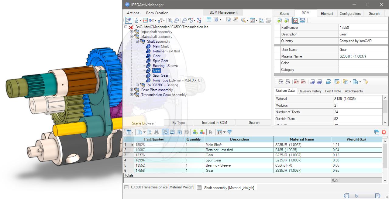
There is also Configurations management, Search functions and a number of small smart tools built in. With this tool you can work directly on the BOM in the 3D scene and add, delete and modify the Properties of parts and assemblies very quickly and easily!
Subsections of ProActive Manager
ProActive Manager Dialog


Drop the ProActive Manager icon from the Tool Catalog into the scene, or click the icon in the Add-ins tab, in the IC Mechanical group; this dialog will open.

In the Left Side scene management, here you can choose how to view the scene browser, in fact the icons in the upper part are used to turn on/off, suppress…While in the bottom edge there are four tabs, the first is the Scene Browser, the second By Type is a tree divided by type of elements grouped automatically into: assemblies, parts, sheetmetals, 3D curves, external links, fasteners and steels; the third tab Included in BOM separates the elements included or not included in the bill of material; finally, the fourth tab Serach containing the results of the search function.
see more here…
On the Right Side there are also here some tabs whose number changes according to what is selected in the browser on the left.There is the Scene tab which shows the properties of the open * .ics file. The BOM tab to manage the data of the bill; the Element tab which shows the geometric data of the elements. The Configuration tab that manages the configuration of the file and finally the Search tab, where you can search and manage searches for elements in the open file.
see more here…
In the Bottom Side of the dialog the Bill Of Materials is shown (normally it is hidden, to show it you have to create a BOM ).Above the BOM grid there are icons for Exporting the BOM, printing it and managing its display, while below, one or more BOM tabs, with the name of the selected file or assembly, and in square brackets which [BOM configuration name] was used to create it.
see more here…
To view the BOM you want, you need to create a configuration and set it in BOM settings to choose what to include, and how to format the different columns, etc.
Subsections of ProActive Manager Dialog
Left panel - Browser

Icons
In the upper left part of the dialog box, there are some icons to control the tree view display:

 Some icons appear in the TreeView to indicate that the elements contains particular information:Assembly Name in Bold Blue Font - it means it has AutoNaming
 - it means it has Attachments
 - it means it has Revisions
 - it means it has PostIt Note
 - it means it has Status Color
 - it means it is a linked file and
  the path.
Actions
 - Select in the Scene the selected TreeNodes
 - Update the TreeViews, Refresh, Expand and Collapse All
 - Select Element in BOM Grid (only active when there is a BOM grid)
 - Hide Selected Elements, Hide Unselected and Show All
 - Ghost Selected Elements, Ghost Unselected, UnGhost All
 - Zoom on Selected ItemEach click rotates the view by 90 degrees, but if the item is selected in the scene, the first click shows it in the browser and in the BOM tab
 - Set Trasparent All Other Parts
 - Suppress All Other Parts
 - Suppress/UnSuppress the Selection
 - Exchange Selection
 - Create new configuration (only active when use Suppress All Other Parts)
BOM Management
icons to manage the BOM:

 - Create BOM
 - BOM Settings
 - Open Settings Dialog…
 - Open BOM Configuration Manager…
Utils
and some utility icons:

 - Search by Properties
 The results will be shown in the Search tab (see bottom of this page)
 - Set TreeView Sort Option
 Sorts by PartName, Creation date, PartNumber or Category; the last option sets the new sorting to the SceneBrowser
 - Search and Replace Text inside elements
 - Rename Children Parts (active only when an assembly is selected)
Tabs
In the bottom edge there are four tabs:
Scene Browser
It is the same tree view as the scene

By Type
Is a treeview divided by type of elements grouped automatically into: assemblies, empty assemblies, parts, sheetmetals, 3D curves, external links, fasteners and steels; it is also possible - with the right click - to Suppress/Unsuppress all elements in the group.

Included in BOM
Shows the elements included in the BOM, or those not included or see them both (with the combobox below you can choose how to see them)

Search
This tab containing the results of the search function;
search for a multiple fields:

search for a Status filter:

or the result of Search by Properties.

Note
For how to set the search function see here .
Right panel - Properties

On the right side there are some tabs whose number changes according to what is selected in the browser on the left.
Scene
This tab shows the properties of the opened file (in the top grid), while in the bottom tab “Scene Properties” you can edit them or add new ones, if you want to always add the same properties in all scenes, see here.

BOM
In the BOM tab, you manage all the data that will be used to compile the Bill Of Materials, such as PartNumber, Description and User Name (you can also change it in the browser on the left, click on the name and click again to edit), also you can set Material Name, Color and Category, while in the bottom of the tab you manage the Custom Data.

 - Search Next Part with the same PartNumber
 - Serach Previous Part with the same PartNumber
 - Set Status Colors on the selected elements see here

 - Include or
  Exclude Element in BOM

(If the icon in BOM is disabled, also the fields PartNumber, Description and Quantity will be disabled.)
 - Set User QuantityIf it’s active, in the grid below the quantity row is activated (the item “Computed by IronCAD” disappears) and the quantity can be entered manually
Available only for Assemblies
 -
-  - Assembly Expansion in BOM
Expand or Treat as Part, for All connected instances or Only for this Assembly

Utility and Custom Data
In the left column, you can enter the Name of the CustomData, or if you click on the dropdown menu, you can choose the name from a custom list (that you can create and modify by clicking on the <New...> field) see here for set default name

While, in the right column enter the Value of the CustomData, again if you click on the drop down menu, you can choose the value from a custom list (which you can create and modify by clicking on the <New...> field), in addition there are two other special fields:
<Get From Parent>
If you select this option, the value of the current CustomData is obtained from the one with the same name from the parent assembly and set in the CustomData value of the part.<Set To Children>
When you select this option, the current CustomData value of the assembly will be set in all child items that have a CustomData with the same title as the assembly.These options only copy CustomData values. Copied values do not remain “linked” to the original selected value
the icon in the name cell
 - Deletes the CustomData field, both the name and the valuethe icon in the value cell
 - Sets and links the current value from an Excel cell
By typing Alt+d in a CustomData or Property field, the current date will be inserted.
Utility Icons

 - Set current UserName using PartNumber
 - Set current UserName using Description
 - Set current PartNumber using UserName
 - Set current Description using UserNameThese four tools also work with an active multiple selection in the browser.
 - Set UserName using CustomValueSchema
 - Set All UserNames using CustomValueSchema
 - Set CustomValueSchemaSets the field to choose to change the user name:

 - Numbering Selected Elements, read more here…
 - Import CustomData, import custom data from Excel file, CVS or Text file
 - Export CustomData, export custom data to a CVS or Excel file (all CustomData or DefaultTitles)
 - Update Excel -> Custom fields, update custom data fields linked to an Excel file, or vice versa.

Custom Data fields that are linked to Excel are yellow and there are two icons in the cell, one to view the Excel file and the other  to remove the link.
Other tabs

In the bottom area of the BOM tab, in addition to the Custom Data fields, there are also tabs for: Revision History, PostIt Note and Attachements.
And here you can add or edit all these properties very quickly.
Element
In this tab you can see the geometric data of the element such as sizebox and position, and it is also possible to change the Material Name and then calculate the volume and weight and the center of gravity (if the selection is a 3D curve, it shows the length of the curve).

Configurations
The tab shows the present configurations of the file and here you can also manage them.To manage the configurations you can also see Configurations Manager.

Search
Here you can search and manage searches for elements in the open file, you can search across multiple fields and with different conditions, you can search only for certain elements by selecting the icons in the top bar, and you can also save the search conditions to reuse them in other files.
 - Start Search
 - Clear Search TreeView
 - Clear Search Grid
 - Add Search Condition
 - Remove Search Condition
 - Save, Delete, Apply Search Condition - Search by Status Colors
 - Include/Exclude Elements in the Search
 - Search Case Sensitive

Note
The results of the search function are displayed in the Search tab on the left see here.
Bottom panel - BOM Grid

In the Bottom Side of the dialog the Bill Of Materials is shown, normally it is hidden, to show it you have to create a BOM.
Icons
Above the BOM there are some icons to control the grid:
 - Update BOM and Import from Excel

 - Export Grid BOM in txt format or in other formats:see here how to set Export BOM

 - Print Preview Grid BOM (open dialog)

 - Print Grid BOM (directly)
 - Autoresize All Columns during resizin of the dialog
 - Auto Fit all the columns of the BOM
 - Save the Template file of Columns Layout
 - Restore the Columns Layout usin Template file
 - Show Parent CustomData to Children Elements
 - Clear Parent CustomData to Children ElementsShow/Clear Assembly CustomData in Children Parts, only if you have enabled the “Inherited by Children” setting in a BOM configuration.
 - Toggle Selection ModeAllows you to select multiple grid cells, useful for copying and pasting them in other areas or in other applications such as Word, Excel…
 - Set Custom Sort

Normally to sort the grid you can click on the column name, with Set Custom Sort you can sort the grid by more than one column.

 - Set Row Filter

When the option is enabled, a new icon appears at the top of the rows, clicking on which brings up a menu for selecting a quick filter or a custom one.

 - Open the BOM in a new dialog, (is up there on the right), effectively detaching the BOM grid in a separate window; this behavior can be set as the default choice in BOM Settings -> BOM Option Grig
 - Close BOM, (is up there on the right) closes the active BOM grid.

At the bottom of the BOM there are one or more BOM tabs, with the name of the selected file or assembly, and in square brackets which [BOM configuration name] was used to create it.
In the example above there are two ones, the first of the entire file and the second of the Shaft assembly only, both with the configuration [Material_Weigth].
To view the BOM you want, you need to create a configuration and set it in BOM settings to choose what to include, and how to format the different columns, etc.
Create BOM

To create a BOM, the file (the red IronCAD icon) or an Assembly in the Scene Browser must be selected, then click the Create BOM button.
The dialog box expands at the bottom and the BOM is shown.For an explanation of the icons, see here.
Each created BOM will appear in a new tab showing at the bottom (if it is not already an existing one, in this case it is updated).

The tab name is composed of the name of the selected file or assembly and enclosed in square brackets the name of the [ BOM configuration ] used to create it.
In the example above there are two ones, the first of the entire file CX500 Transmission.ics with the configuration [Default] and the second of the Shaft assembly only, with the configuration [Material_Weigth].
Tip
To close the active BOM tab, click the red cross icon on the right side.
Config BOM

To create a custom BOM (to set the data you want to show and which types of attributes to include in the bom) click on the BOM Configuration Manager… button.

This is the default configuration with the three standard lines; PartNumber, Quantity and Description.
In the left part of the dialog there is the list of configurations, while on the right the list of attributes of the selected configuration (which will generate the bill of materials).

To create a new configuration click on the first button on the top left, then name the new configuration by two slow clicks on the name to change it.
To add more rows, click in the next available row in the Title column and enter a name. The title is the name of the column itself in the BOM.

Then select - in the Get value from… column - the property (Part Property) to link to that column in the BOM. A drop-down menu appears where there are several properties to choose from.
Show all Variables available in Column Get From:
For some properties it is necessary to fill in the Option column.
| Variables Type | returns | option Name |
|---|
| Quantity | quantity of the elements | |
| PartNumber | part number of the element | |
| Description | description of the element | |
| CustomData Value | value of the CustomData | the name of CustomData contained in the element, if different respect the Title |
| Material Name | material name of the element | |
| User Name | name of the element | |
| Sizebox Height of Element | total height of the element | |
| Sizebox Length of Element | total length of the element | only for sheetmetal, SM_UNFOLD = returns the length of the unfolded sheet |
| Sizebox Width of Element | total width of the element | only for sheetmetal, SM_UNFOLD = returns the width of the unfolded sheet |
| Thickness of SheetMetal | thickness value of sheet metal | |
| Total Weight of Elements | weight value of all elements | |
| External Linked Status | status of external link element true/false | |
| External Linked File | path of the external link element | |
| Scene Properties | file property value | the name of Property contained in the file, if different from the Title |
| Combo 1 | the result is get from an expression string. | ex: <Description> - <Sizebox Length> x <Sizebox Width> |
| Longest Value of Sizebox | the longest value (among L W H) of the sizebox | |
| Parameter Value | parameter value | the name of Parameter contained in the element, if different from the Title |
| Expression 2 | this field evaluate an expression using the MSExcel syntax | ex: CONCATENATE ([Description] , "-" , "Tot.Weight gr.=" , ([Qty]*[W]*1000)) |
| Expression Hidden 2 | like expression, but the result is not visible in the grid | ex: [Qty]*[W]*100 (Qty and W are Title) |
| Position X - Relative | X value of the relative position | |
| Position Y - Relative | Y value of the relative position | |
| Position Z - Relative | Z value of the relative position | |
| Position X - Absolute | X value of the absolute position | |
| Position Y - Absolute | Y value of the absolute position | |
| Position Z - Absolute | Z value of the absolute position | |
| Row Counter | this value BOM row index | + starting value (optional, otherwise it starts from 1) |
| Surface of Element | surface value of all faces of the part | insert unit of measure: mmq cmq mq ftq inq ydq (default mmq)in case of tube, rectangular, and square hollow steels calculate only the external surface+TopFaces also calculates the area of the faces at the top and bottom of the steel |
| Volume of Element | volume value of the element | |
| Weight of Element in Water | weight value of the element in water | |
| Mass Density | mass density value of element | |
| Weight of Element | weight value of the element | to calculate Steels without cuts <STEEL_RAW> |
| Length of Sweep | value of the length of the guide curve of the sweep | |
| Where Used | the part number of the parent assembly | |
| Status Color Marker | the status of element | see here how use Status |
| Area of Unfold SM Part | the area of unfolded sheet metal | 0 or empty for real unfolded face area1 for bounding box unfolded face area |
| Perimeter of Unfold SM Part | the perimeter of unfolded sheet metal | 0 or empty for external perimeter1 for internal perimeters (es. the holes or cuts)2 for the sum of external and internal perimeters |
| SMBend info | obtain the number and radius of bends of a sheet metal part | ONLYQTY for obtain only the number of bends |
| Price in IPROBOMPriceList | obtain the price stored in the file IPROBOMPriceList.xlsx | see here how use PriceList |
| Element ID | returns the ID of the element | the text entered as an option will be prefixed to the ID number |
| Field | Tags accepted |
|---|
| 1. Combo | Insert in the Option field the required values enclosed in < > brackets, brackets and contained string will be replaced by the value, all other text will remain unchanged, tag available are: <PartNumber> <Description> <@CustomName> <Sizebox Height> <Sizebox Legth> <Sizebox Width> <MaterialName> <Quantity> <ElementName> |
| 2. Expression | Insert in the Option field the required expression, the value of Title must to be enclosed in [name of title] bracket, all MS Excel expression are valid |
| all field | if you add <ADDTOCUSTOM> in any Option field, the Title of the field will be added to the CustomData and will be filled with the value found in Get Fromif you add <SUM> in any numeric Option field, it will sum all numerical values |
The Format column set the format to display data in the BOM and is automatically filled with the correct value:
%s for text string,%i for integer,%f.2 for floating where the number after the dot indicates the number of decimals,%fc.2 for custom floating where the character after fc is the decimal separator.
The Count By column is used to control which property is used to count parts/assemblies with similar properties. The number is added and displayed in the list column of the BOM (Quantity) unlike the bom in the 2D drawing, any value can be used here!
With Ref. for StructuredBOM, you can control which property should be primary, using multiple selections in Count by. It is therefore possible to summarize in the BOM with more than one property (but it is only possible when using the Multi Level BOM type).
Inherited by Children means that this field (if “Get Value from…” is set to “CustomData Value”) can be used to set the value of the father in the child parts; it should be used in conjunction with the commands in the BOM grid “Show Parent CustomData to Children Elements” and “Clear Parent CustomData to Children Elements”.
Sum Column allows you to sum all the values of the column and in BOM grid a row with the totals of this column will be added.
The order of the Title column from top to bottom is also the order of the columns of the BOM grid from left to right.

The icons on the left are for: 
- create a new configuration
- save the configuration
- save configuration with a new name
- open a saved configuration
- delete configuration
The icons on the right are for: 
If you turn on the advanced setting, the dialog box expands down and there are three sections here:

Export BOM
If you directly export the BOM to txt or cvs file, you can set the separator character for the fields, the character of the decimal separator, the path (if the path is not set, the file will be saved in the current folder) and the name of the file to export the BOM, see here how for Export BOM.
MSExcel Export Settings
If you export the Bill of Materials to an Excel file, you can designate a specific initial template file and sheet for the BOM to be exported to. This feature allows for greater customization and efficiency in the export process.
Folder for VirtualCode Datafiles
If you want to replace real PartNumbers with virtual codes, enter the search path here.
Subsections of Config BOM
Management of Price

Possibility to manage the prices related to elements in the ProActveBOM. All the prices and the rules about the price calculation are store in the file IPROBOMPriceList.xlsx, stored in the ..\Prefs\ folder of IC-Mechanical.
The meaning of the fields is:
- PriceCode/PartNumber: This is the key search about the price; it could be a custom data named PriceCode or, if the custom doesn’t exist, the PartNumber of the element.
- Price: It’s the unitary price to be used for the elaboration.
- Unit of Measure: That is a integer value that define the way to calculate the final price; at the moment, the available values are:
1 - Unit Price2 - by Linear Meter3 - by Square Meter4 - by Cube Meter5 - by Kg Weight20 - by Linear Millimeters30 - by Square Millimeters40 - by Cube Millimeters
In order to have the Price reported in the BOM, it’s necessary to define a field in the BOMConfig related to the Price:

- All the parts or assemblies (treated as part) are elaborated in order to get a price.
When the field related to Price is defined, the elements in the scene are elaborated in this way:
- If the element has a custom data named PriceCode, this will be used to search a correspondence with the first column of the Excel file.
- If PriceCode is not defined, it will be used the value of PartNumber.
- If in Option of GetValue in IPROBOMPriceList you use
<MATERIAL> tag, will be used the value of Material. - If in Option of GetValue in IPROBOMPriceList you use
<PARTNAME> tag, will be used the value of PartName. - If in Option of GetValue in IPROBOMPriceList you use
<PARTNUMBER> tag, will be used the value of PartNumber. - If in Option of GetValue in IPROBOMPriceList you use
<MyCustomTitle> tag, will be used the value of MyCustomData
- After the calculation, the resulted price will be reported on the grid.
- If the correspondence is found, the price is calculated using the properties (Unit=quantity, Linear=length, Square=area, Cube=volume, Kg=weight) of the element.
Info
Price calculation is also done using the “formula” in Excel’s Price column; this allows the use of a formula within square brackets [ ], where the valuation variable is defined by the % character.
For example, one can evaluate the price based on whether the length (or weight) is greater or less than a given value.
Examples of formula are:
[IF(% > 200, 20, 10)][SWITCH(%; 100;10;200;20;300;30; 500)][IFS(% >= 300; 30; % >= 200; 20; %>=100; 10; TRUE; 1)]
As example this formula:
[IF(% > 200, 20, 10)]
with Unit of Measure set to 20,it means:
If the calculated Length is greather of 200 mm, use the price 20. In other case use 10.

Note
When the element is an assembly, all the children’s elements are evaluated, and the sum of the prices is reported in the grid.

BOM Settings and Preset

Before creating the BOM, you can select a configuration to use, a filter by category, the types of items to display in the BOM and some other options. First, click the drop-down menu (arrow) on the BOM Settings button.

Choose which BOM configuration to use (how to create the configuration).

Choose an optional filter by Category (how to create the Category filters).

Choose an optional filter by Color Status (how to use Color Status).

The BOM Type of the flyout menu allows you to check which parts and how should be displayed in the BOM and how to create the BOM itself.

The BOM Options of the flyout menu allow you to include additional BOM data and set other options.
Subsections of BOM Settings and Preset
Status Color Filter
The Status Color Filter in the pop-up menu allows you to choose which parts to display in the BOM based on their assigned status.

You can choose to include/exclude all states or just some of them.
For how to activate the display of the Color States in the TreeView see here BOM Settings Dialog

For how to assign color status to elements, see here, for how to use the status in the BOM, see Config BOM, and for how to search for elements based on their status, see here.
BOM Type
The BOM Type of the flyout menu allows you to check which parts and how should be displayed in the BOM and how to create the BOM itself.

Top Level BOM
Displays only the elements in the top level of the Scene Browser or the elements below the selected assembly.
Only Parts BOM
Show parts only and excludes all assemblies that use the Expand option in BOM;
however, assemblies that use Treat as Part are considered “parts” and appear in the BOM.
Flat BOM
It shows a flat structure as BOM Parts Only, but here you can also choose to include or not include the assembly using Treat as Part or Expand.
And whether to include in count the children parts of Assemblies not in BOM.

With the Options menu you can select how assemblies using the Treat as Part setting should be handled and whether they should be shown (or not shown) in the BOM.
Treatment
- Treat as Assembly - forces all assemblies set to Treat as Part to expand (so ignore treats as part).
- Treat as Part - then use Treat as Part just as they are set.
Add to BOM
- Add the item to the BOM - then show these assemblies as parts in the BOM.
- Don’t add the item to the BOM - so do not show these assemblies in the BOM.
Structured BOM (Stop on Assemblies Treated as Part)
It does not show parts that are included in assemblies set as Treat As Part. The generated BOM will manage the element numbers in different columns (Level 0, Level 1, etc.) thus re-applying the Scene Browser tree.
Multi Level BOM (Force Expand on All Assemblies)
Shows all elements below the selected layer, even if assemblies use the Treat as Part setting. This is a great way to create a complete list of projects with all components.
Multi Assemblies BOM
Automatically create multiple tabs with BOMs, where each tab is a BOM of each assembly in the 3D file.
The Level n° option allows you to set the depth of the search in the tree.
A super fast way to create multiple BOMs at once ;-)
Multi BOM by Category
Automatically create multiple tabs with BOMs, where each tab is a BOM divided by Category.

Click to show content from YouTube.
(read the service's privacy policy)
Tip
If you want to create a specific BOM configuration for each category, you must give the Configuration the same name as the category.

BOM Options
The BOM Options of the flyout menu allow you to include additional BOM data and set other options.

Include All CustomData
Adds a column for each custom data value found in parts/assemblies. Items that do not have a certain custom value will have one blank box per row, which can also be manually filled in directly in the paragraph list, it’s also an easy way to fill in the BOM.
It also shows the Unfolded SheetMetal Parts in the BOM. By default these are not displayed in IronCAD unless they are explicitly unfold.
Include Suppressed Elements
It also includes all the off (suppress) parts/assemblies, so you can get a complete list of everything in the 3D scene.
Counts Parts using Assembly Number
It means that the number of a parts is calculated from the number of the assembly in which it is included and not how many parts are actually contained in the assembly.
Include Element having Empty PartNumber
Items that have no item PartNumber are also counted and give them a “ND_xxx” temporary serial number. This number is not actually saved in the item but is only displayed in the BOM.
Include Element having Empty Description
Items that have no item Description are also counted in the BOM.
Elaborate Children of Not in BOM Assemblies
Also considers parts of assemblies not in the BOM, so they are processed and shown in the BOM.
Compact Layout for Structured BOM
Merges the Levels columns of the BOM Structured and Multi Level into one and creates the numbering based on the nesting of parts and assemblies ex. 1, 1.1, 1.2… 2, 2.1, 2.2, 2.2.1, 2.2.2…
Set Category Filters
Set up filters for categories, so you can create BOMs that include/exclude certain categories.

Categories can be created with the Category tool or in the BOM tab of the ProActive Manager.
Update Excel->Custom during the BOM
If there are CustomData linked to the Excel file, they are updated automatically.
BOM Settings Dialog

In the BOM Settings dialog you can set the default values for the BOM Type and BOM Options for the Grid,

and for the export options to Excel.

File and CustomData Properties
You can also always and automatically assign additional properties to all files you open in: Default File Properties and/or Default CustomData Properties.

In CustomData, you can choose to assign them to assemblies only, parts only, or both; and the field name will be set automatically to the assembly or part see here for more options.
Work in BOM

Once the BOM is created, you can easily see which parts and assemblies do not have certain types of attributes or values and write them directly into the BOM cell.
All values written in the cells (which are actually the properties and customdata of the parts/assemblies) are added directly to each object, so there is no save button.
In the upper right part of the window is the BOM tab; there you can see (and also edit) all the properties of the selected part/assembly.
To view the properties of another part/assembly, double-click on another row in the BOM or select another part of the tree.
Changes made to the BOM grid are reflected in the BOM tab.
Double-clicking on a BOM cell updates and selects the corresponding element in the Scene Browser.
Export BOM

On the left side, directly above the BOM grid, there are three buttons dedicated to exporting and printing.
 - Export Grid BOM in txt format or in other formats:
You can choose between:
- MSExcel - exports the BOM to an Excel file
- This item is visible only if multiple BOM sheets are open:
- all Sheets to MSExcel files - exports all BOMs to separate Excel files.
- all Sheets to a single Excel File - exports all BOMs to a single Excel file with each BOM in its own sheet.
- PDF - exports only the BOM grid
- PDF with Preview - exports the BOM grid and generates a preview of the element for each row
- XPS - exports only the BOM grid
- MSWord - exports only the BOM grid
- CSV - exports only the BOM grid
- Open File Automatically On Export - is an option that opens the file after exporting.
Tip
For exporting to Excel you can activate multiple options such as two preview types and file properties, see here.
 - Print Preview Grid BOM (open dialog), creates a preview where you can see how the BOM grid looks on the press sheet and you can also print directly to the default printer.
 - Print Grid BOM (directly), prints directly to the default printer without any preview.
If you want a different order of the grid columns, you need to open the configuration manager and change the order in the configuration list and then update the BOM again.
Add Post-It Note
 The Add Post-It Note command allows you to add a written note to a part or assembly in the scene.

Operativity
- Drop the tool on the part,
- A dialog box appears where you can add the date, username and note.
 At the end of the operation close the dialog box, an icon with the post-it symbol appears near the anchor to indicate that an note is associated with the part.

To manage note (view and edit ) right-click on the part and choose Open Post-It Note…
While to delete Note, choose Remove Post-It Note.
Tip
To manage more easily which notes to delete, drop the tool with the right mouse button in the scene, a dialog box shows all the notes and here you have a button to delete the ones you want.

Add Attachment

The Add Attachment command allows you to attach a file or web page to a part or assembly in the scene.

Click to show content from YouTube.
(read the service's privacy policy)
Operativity
- Drop the tool on the part,
- For the assembly, first select it and then drop the tool into scene.
If you choose to attach a file, you can decide whether to connect it externally or embed it in the 3D file (in this case pay attention, the file of the 3D scene will become larger).
In the case of an external linked, the user can decide to copy the linked file to the 3D scene folder.

The elements that have attachments are identified with the following icon:
To manage attachments (view, edit or delete), right-click on the item and choose Open Attachement … from the item menu.


Click to show content from YouTube.
(read the service's privacy policy)
Revision Manager

The Revision Manager tool allows you to manage the revisions of parts and assemblies of the entire scene.

Click to show content from YouTube.
(read the service's privacy policy)
The tool must be dragged to an empty area of the scene.

The dialog box is divided into three areas, on the left the scene browser structure, on the top right the information on the selected part, on the bottom right the revision information of the part.
The buttons above the scene browser allow you to:
- identify in the browser the part selected in the scene;
- update the TreeView;
- hide selection, hide unselected ones, show all;
- zoom the selection (click cycling between standard views).
The two buttons on the right allow you to:
- export the information of all the parts with revision to an excel file;
- setting up revisions.
Here you can choose the numbering mode (letters or numbers)
the order of the review tabs and whether to export the images to the excel file as well.

At the bottom, we have two tabs: Scene shows all parts, Revisions shows only parts with revision.
Note
 The item that has revisions is identified in the scene browser with this icon placed before the name.
Add Revision
In the Revision History section, clicking on the + button adds a revision, here you can enter the validity date, username, description of the revision and any notes.

If there are any revisions, by clicking on the relevant tab you can see the related info; to the right of the date there is the button that allows you to open the file containing the revision.

Note
When creating a revision, the part/assembly file is automatically saved in the Revisions folder inside the project folder, the file name will be: PartName _ Revision _ date.ics
Manage Revisions

To manage the revisions, double click while holding down the Shift key in the gray area next to the icons,

new icons will be appear:
 - Edit the current revision
 - Remove the selected revision
 - Remove all revisions
Views Manager
Useful tool for saves and restores camera status, active configuration and item visibility. This tool also stores the suppression status of the elements. It is a kind of “enhanced” Camera and Configuration Save, with a preview image and some text fields to use for documentation. All this information (images and text) can be exported to an MSExcel or MSWord document.
Operativity
- Drop the tool into scene,
- Adjust the view, hide or suppress unnecessary elements , or select the configuration and then click Save Current View/Configuration,
- Add view title, description and note,
- Repeat step 2 and 3,
- Export to MsWord or MsExcel,
- or save all images in one folder.
The buttons are used for:
- Move the saved view Before or After,
- Save the current view,
- Update and save the selected view,
- Delete the current view,
- Set the size of the image to be saved,
- Export the History of Views,
- Export all images in one folder.
Click to show content from YouTube.
(read the service's privacy policy)
In the left side of dialog there are a buttons for:
- set the target camera,
- use TriBall for set target point,
- set the view orientation with Z axis,
- set angle of rotation view,
- buttons for rotation by angle,
- set step of pan view,
- buttons for move view by step.
Click to show content from YouTube.
(read the service's privacy policy)
Info
You can use IPROCamera Manager - Place IPROCamera to create, place and manage cameras.
Configurations Manager


Tool for easy configuration management. You can rearrange the order, create, rename and delete configurations, you can activate the chosen configuration (also by double clicking on the name in the grid).
Info
If there are externally linked files with configurations, see here to manage them.
Operativity
- Drop the tool into scene, and choose what to do:
- Create New Configuration:


Click to show content from YouTube.
(read the service's privacy policy)
Managing Configurations and externally linked files
If there are externally linked files that themselves contain configurations, the dialog box changes, two new tabs are activated, and an option to manage the behavior of configurations between the main file and the linked files.

Apply Configuration to External Links: this optionallows you to apply configuration to all external linked files.
Note
The default behavior is to apply the same configuration names to external link files (so linked files must have the same configuration name as the main one).
Relation Between Link Configurations: in this tab you can define the relationships between external configurations and the main file configuration, so you can choose which configuration of the linked file to associate with that of the main file.

- External Link Configurations: in addition, the tab allows you to directly apply the desired configuration of the externally linked file.

Set Category

Set Category to one or more elements.

Operativity
- Select the elements you want to assign to a category,
- Drop the tool into scene,
- Chose a category from a menu and confirm.
The buttom to the right of the menu, opens a dialog for editing categories.

the Categories.dat contains this data and is located in the ..\Prefs folder.
Set Color

Set Color to one or more elements.

Operativity
- Drop the tool on the part,
- Or Select the elements/assemblies you want to assign a color to, and drop the tool into scene,
- Chose the color from a menu and confirm.
- if check a Replace Surface Style, the surface that has a different color/texture such as a thread hole will also be colored.
The buttom to the right of the menu, opens a dialog for creating a Color group and/or editing colors.

The Group of ColorNAME.dat files contain this data and are located in the ..\Materials\Colors folder.

 Command useful for managing sheet metal parts to change type and thickness based on the type grouping or individually one by one.
Also you can set the Description using the Stock Name and Code as Material.
Operativity
- Drop the tool on the sheet metal part to change type and thickness,
- Drop the tool into the scene to manage type and thickness for all sheet metal parts.

Click to show content from YouTube.
(read the service's privacy policy)
Config by Property
The Config by Property tool allows you to create Configurations based on certain Custom Data present in the elements of the current scene.
The dialog box is divided into three parts, the upper one there are icons for deleting, adding or removing the custom search rules, an icon to save the search presets, and a combo box to choose presets saved; in the middle, the grid with the customdata to search inside the scene, and at the bottom a text field to specify the name to be assigned to the configuration.

Click to show content from YouTube.
(read the service's privacy policy)
IPROCamera Manager

This tool is useful for managing IPROCamera, setting the FOV angle, rotation, and position of the selected camera.

Operativity
Drop the tool on the scene,
select camera from the drop-down menu: 
choose the correct FOV Angle (Field of View): 
adjust the camera position. 

Click to show content from YouTube.
(read the service's privacy policy)
Info
When you close the Camera Management dialog box, you can return to the previous standard view and choose to activate the display of all IPROCameras, so that you can easily reposition them with the Triball.

Tip
This tool, used with View Manager is useful to create images or view for presentations or documentation.
Place IPROCamera

This tool allows the user to place some IPROCamera parts in the scene and, when required to look at the model using from their position and height. Every IPROCamera can moved using the TriBall.

Operativity
- Drop the tool on the scene,
- set the camera parameters: name, height and FOV angle (Field of View),
- whit TriBall adjust positioning.

Click to show content from YouTube.
(read the service's privacy policy)
Note
All cameras place are grouped in a special assembly named IPROCameras, you can use IPROCamera Manager to manage cameras.


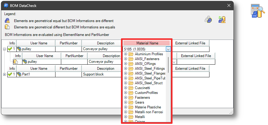
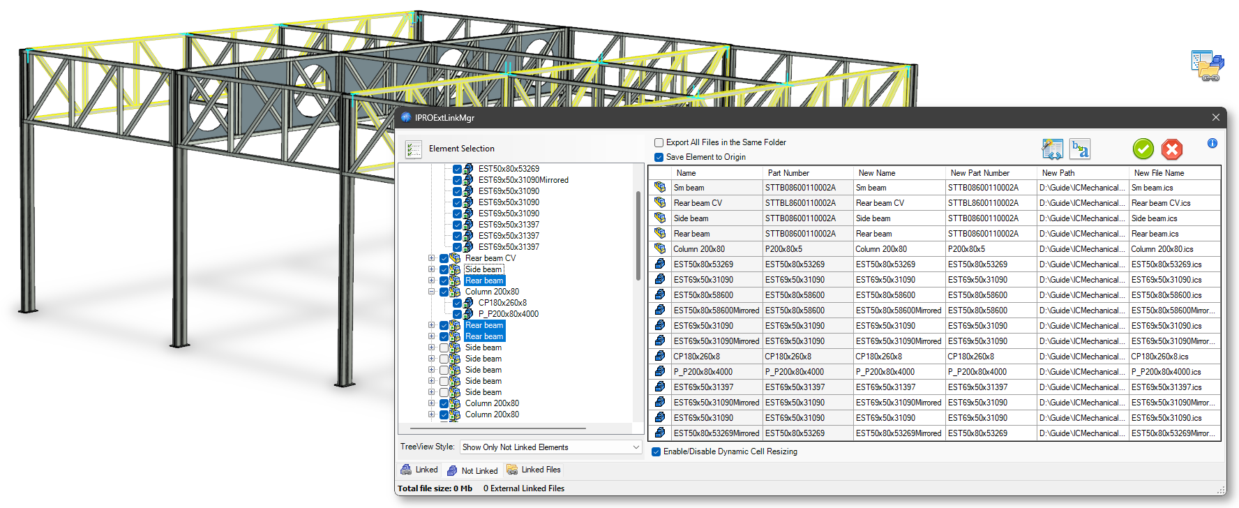
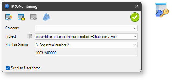
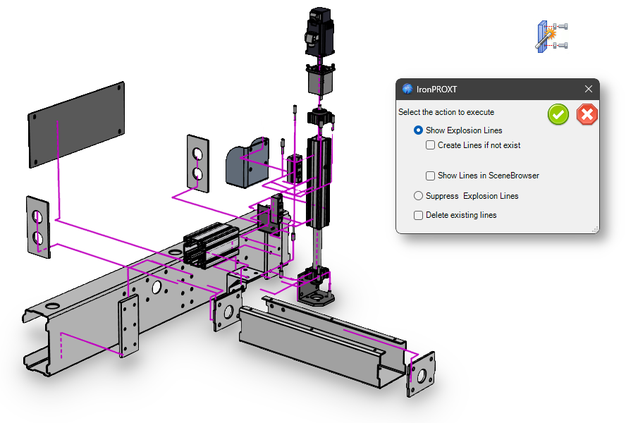
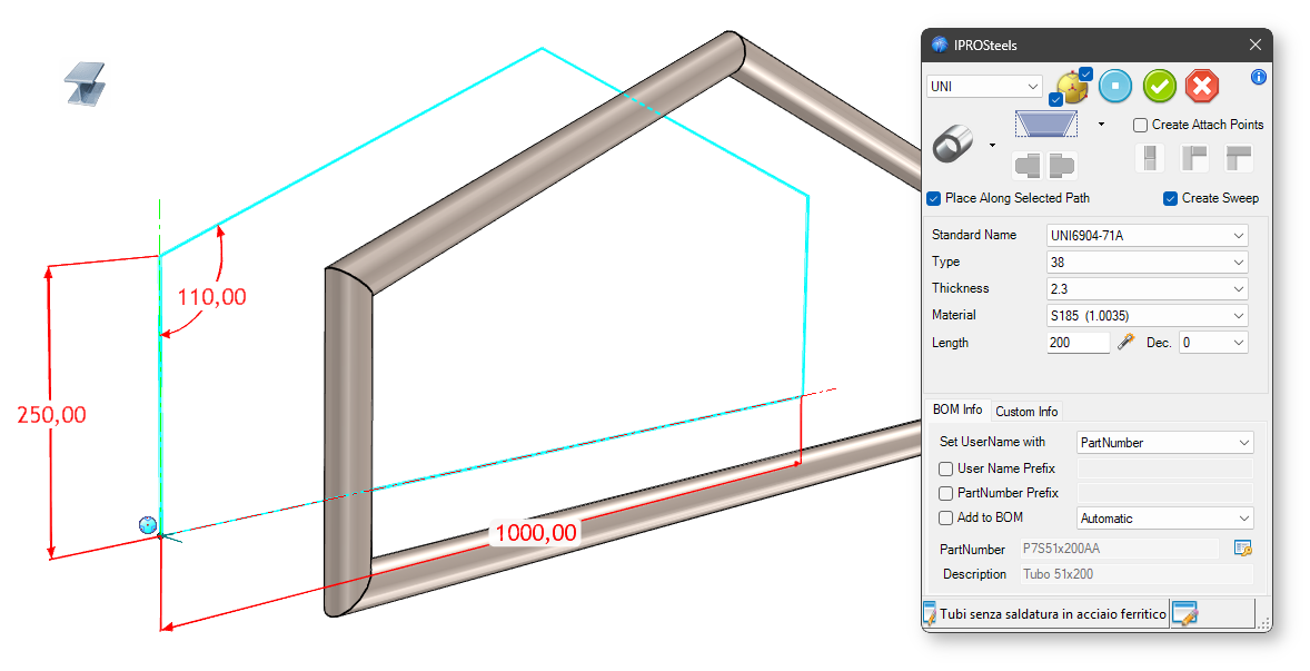
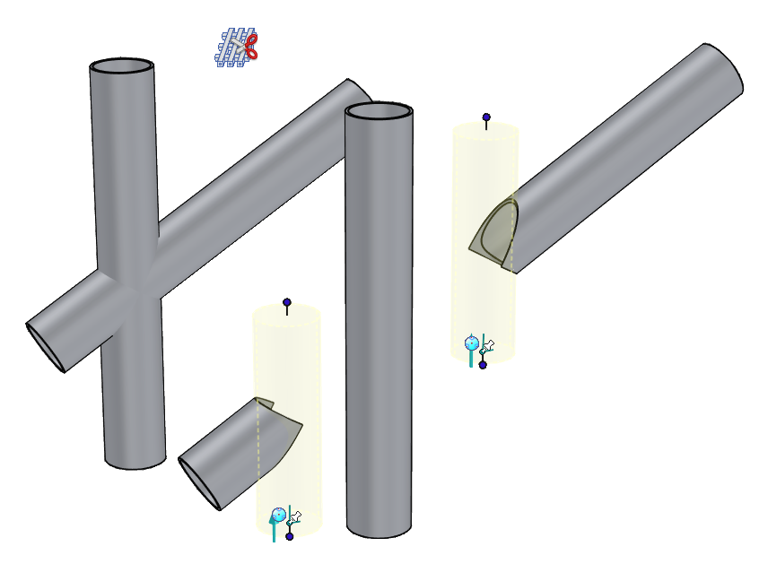
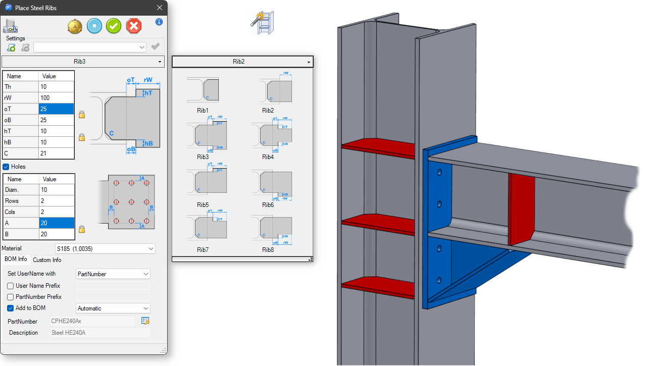
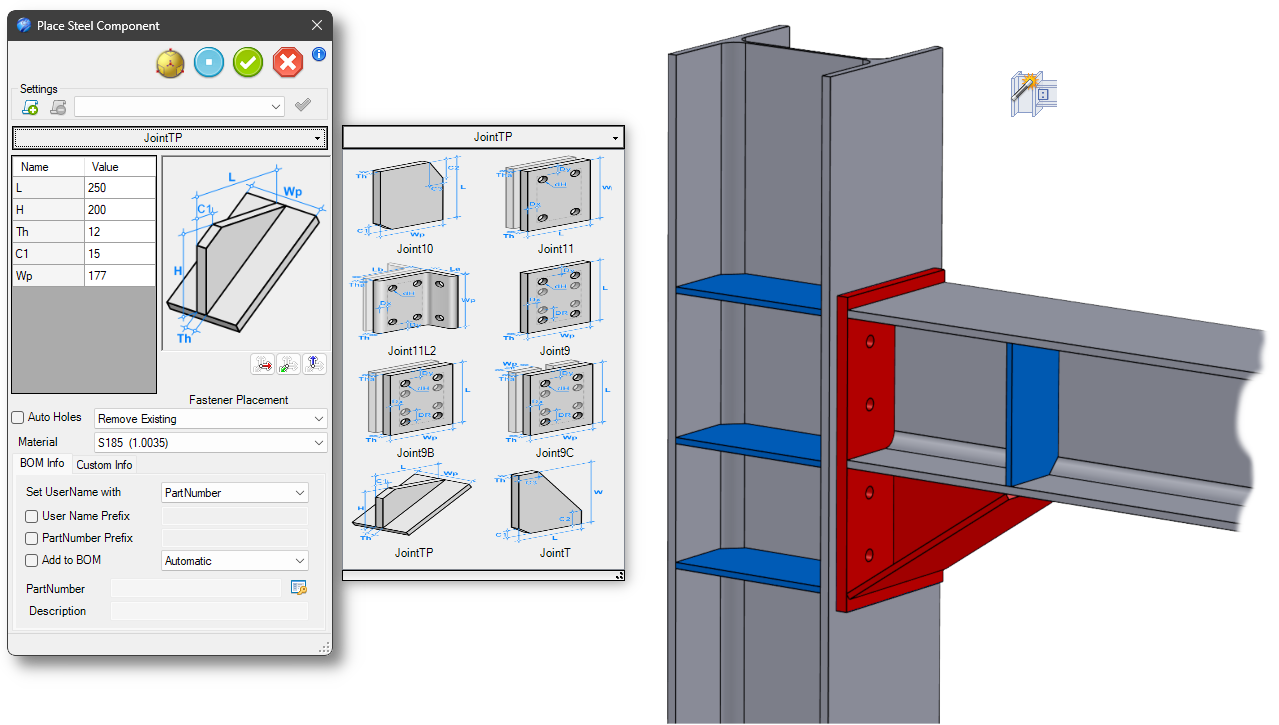
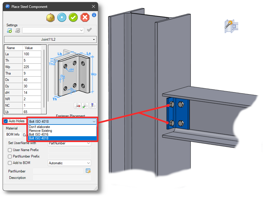
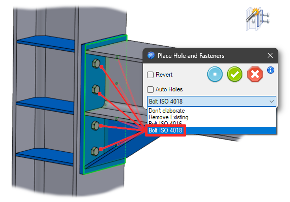
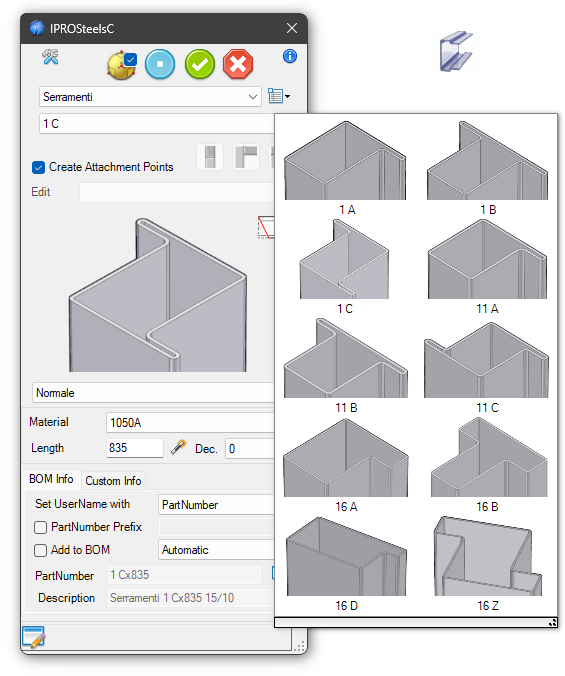

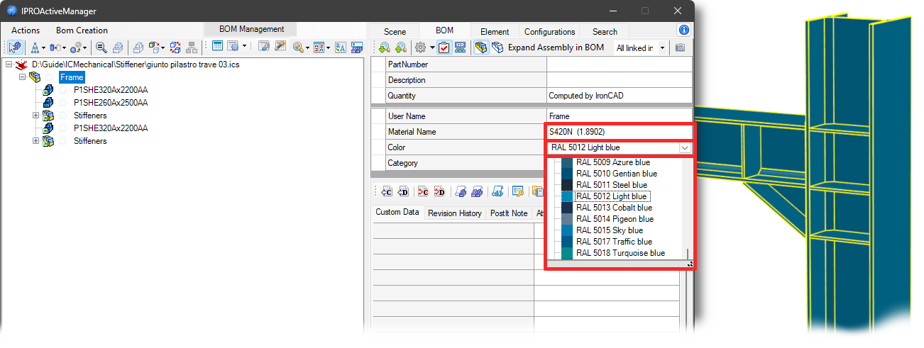
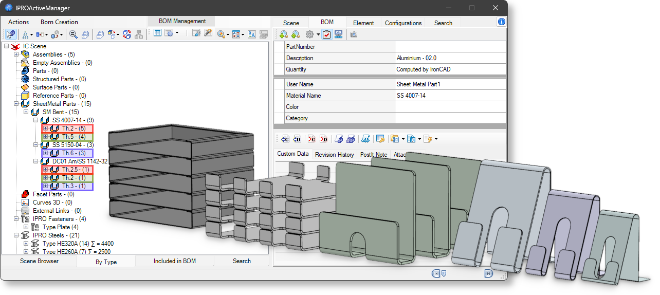
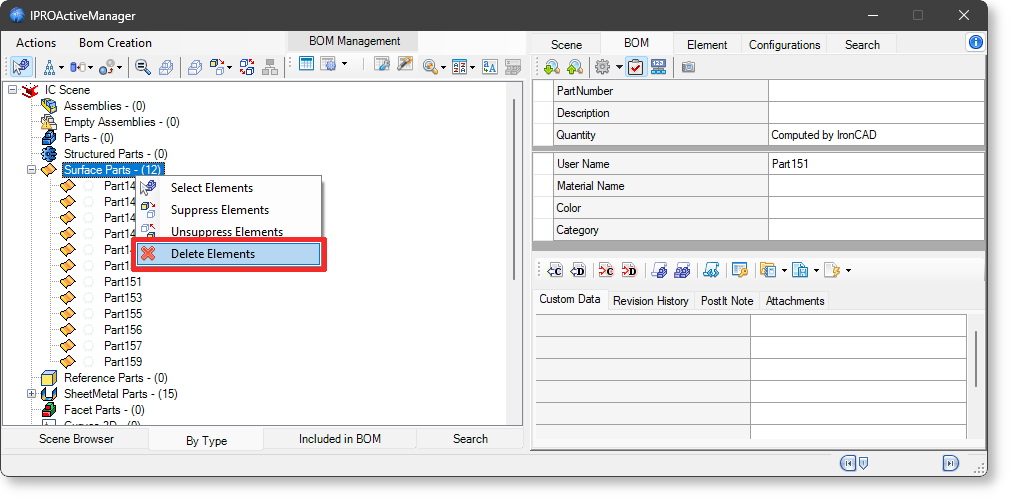
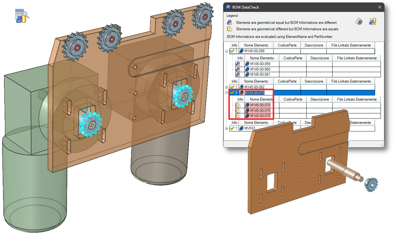
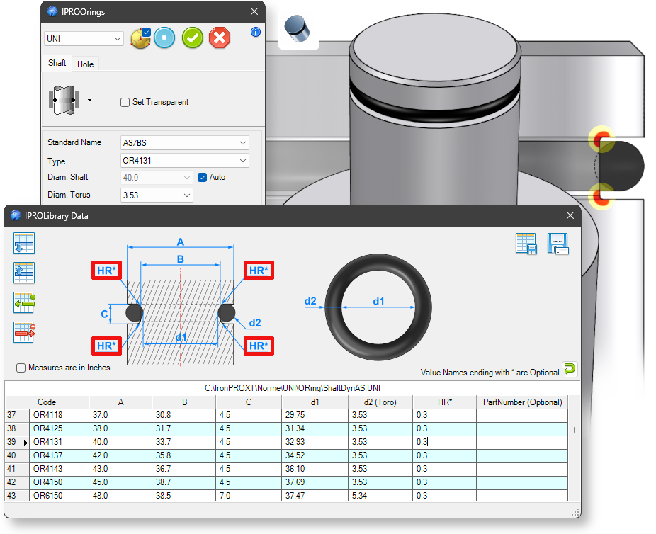
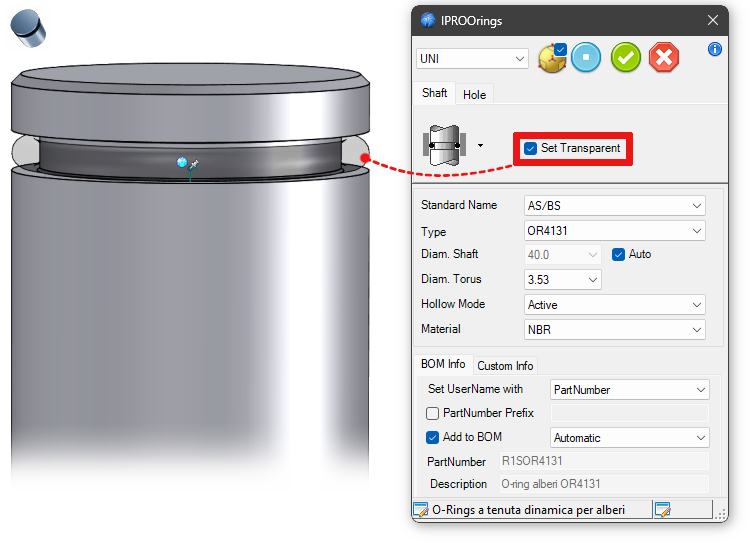
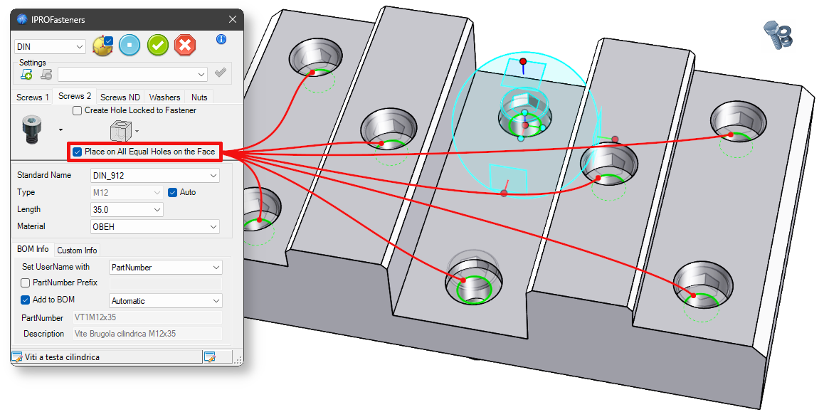
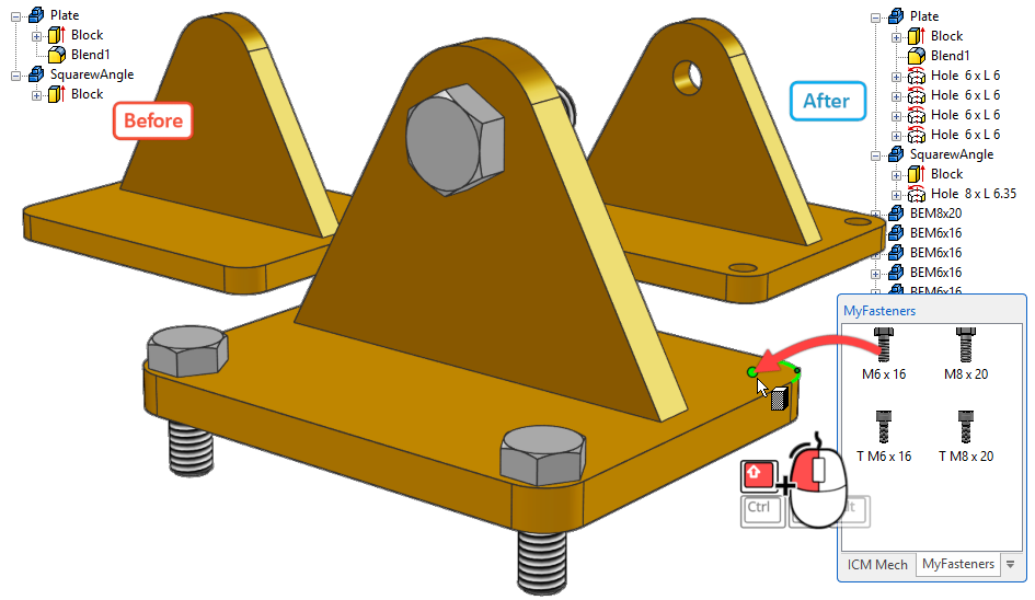
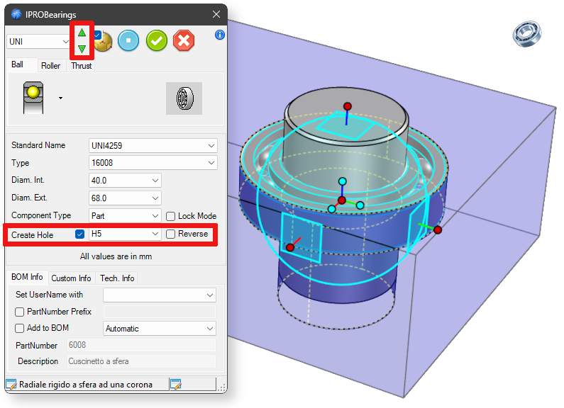
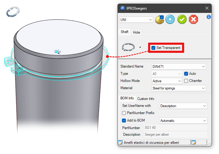
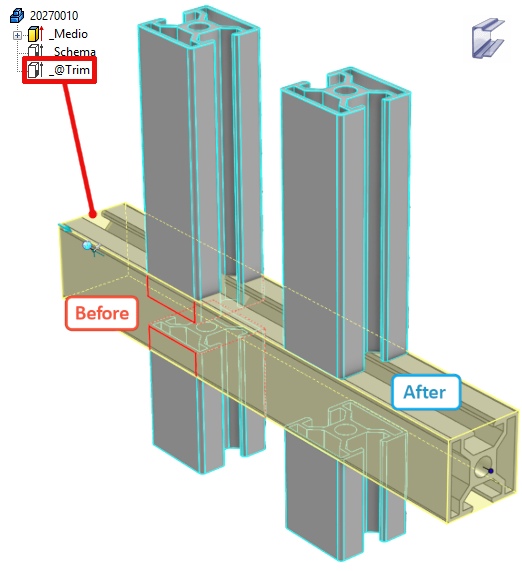
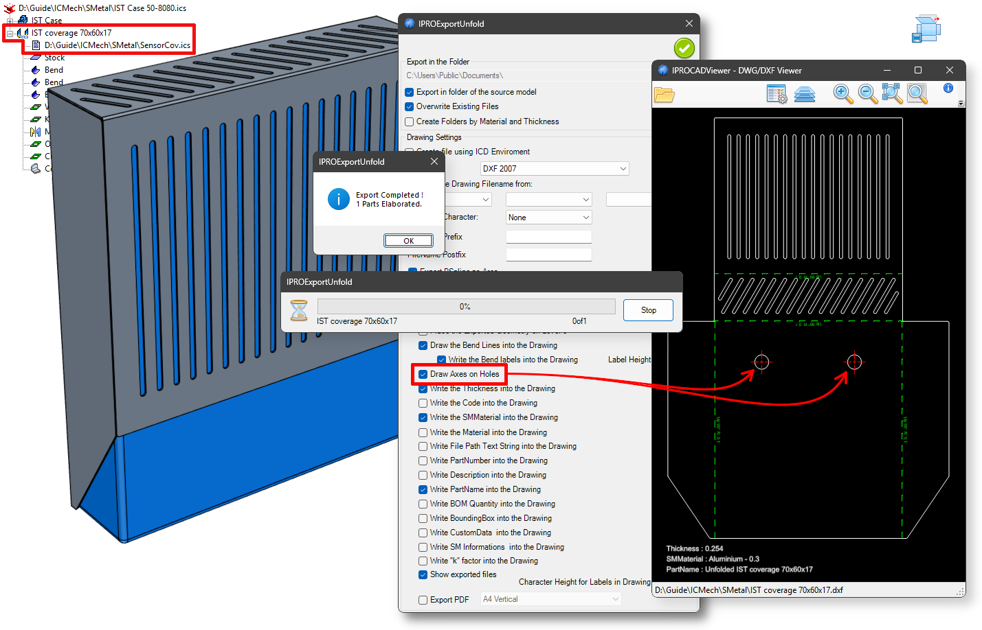
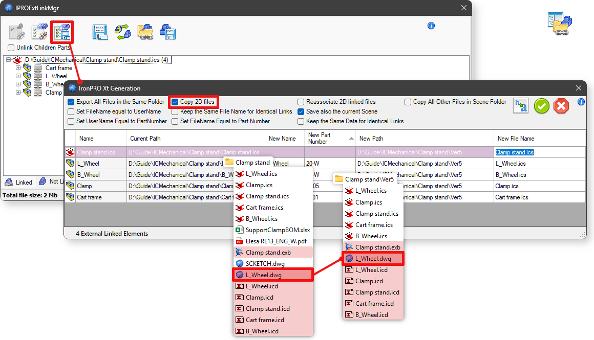
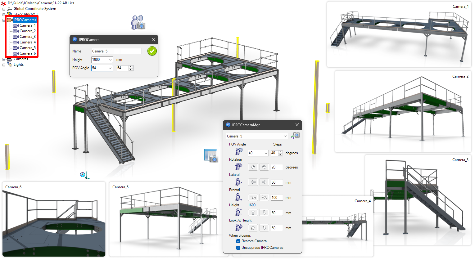

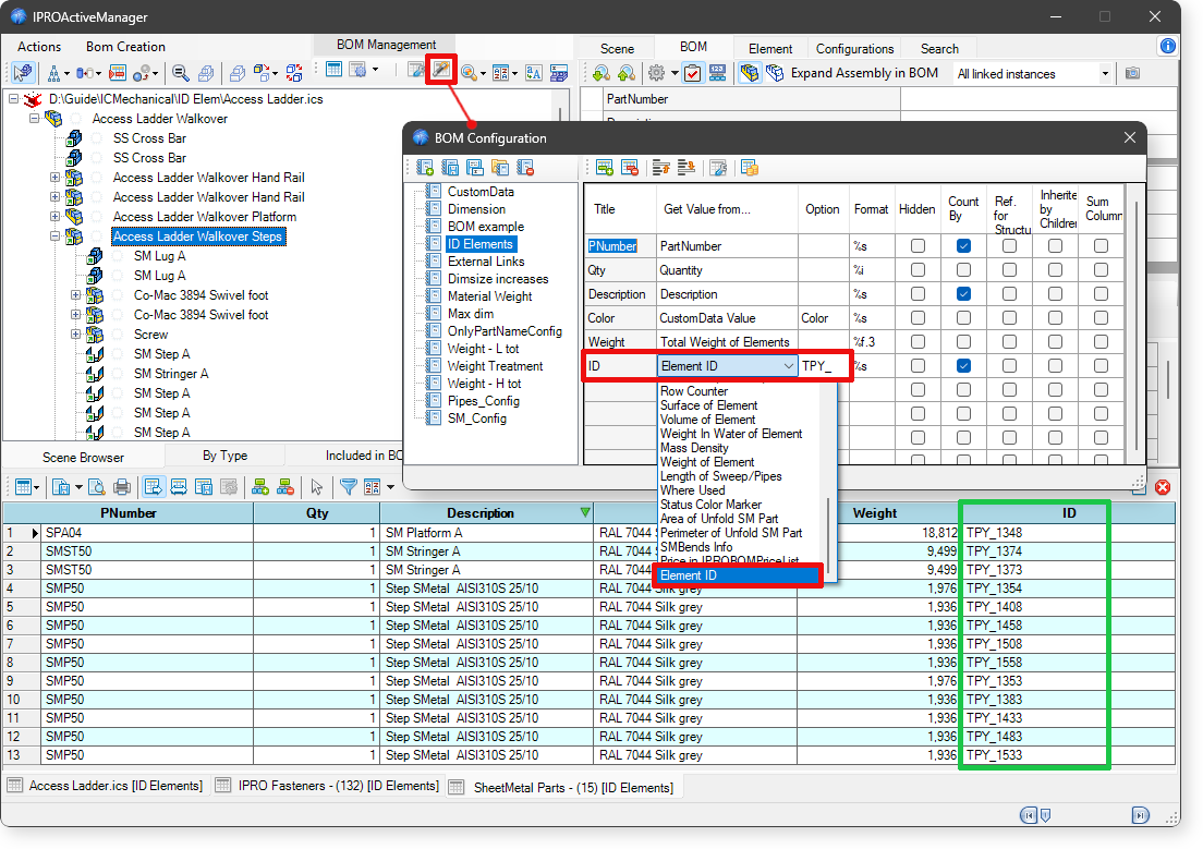
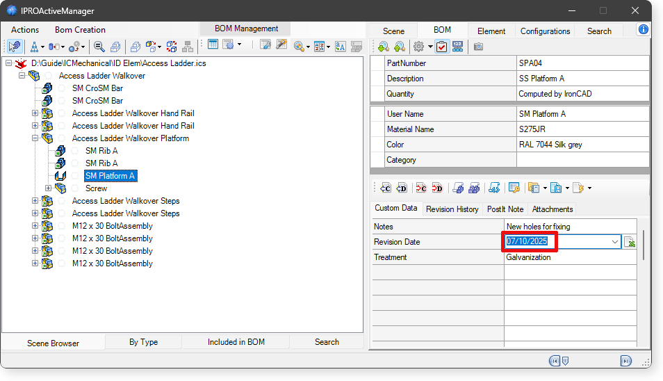
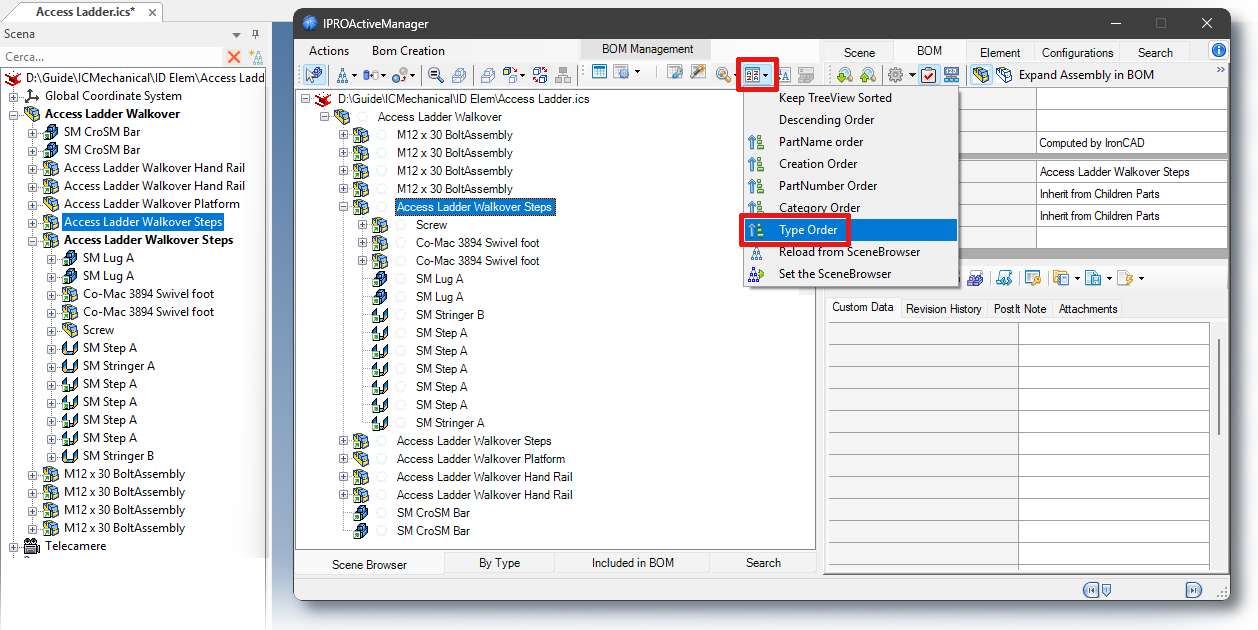
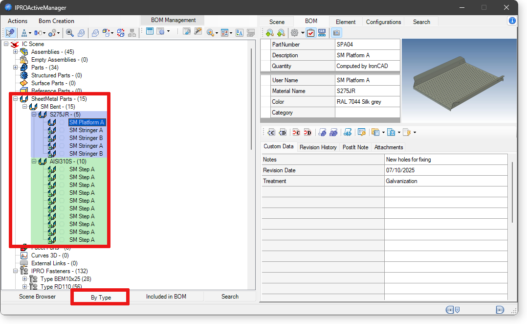
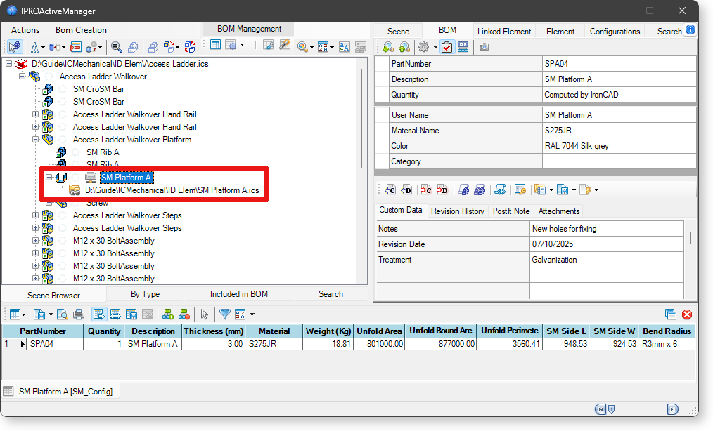
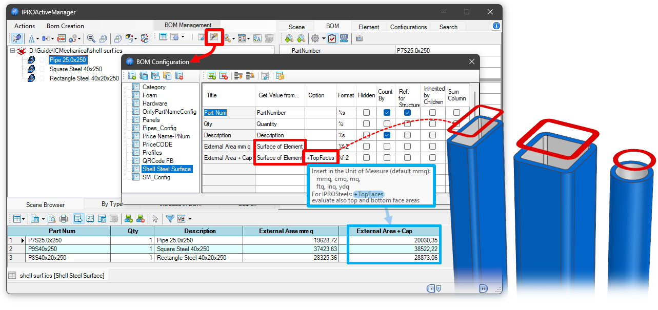
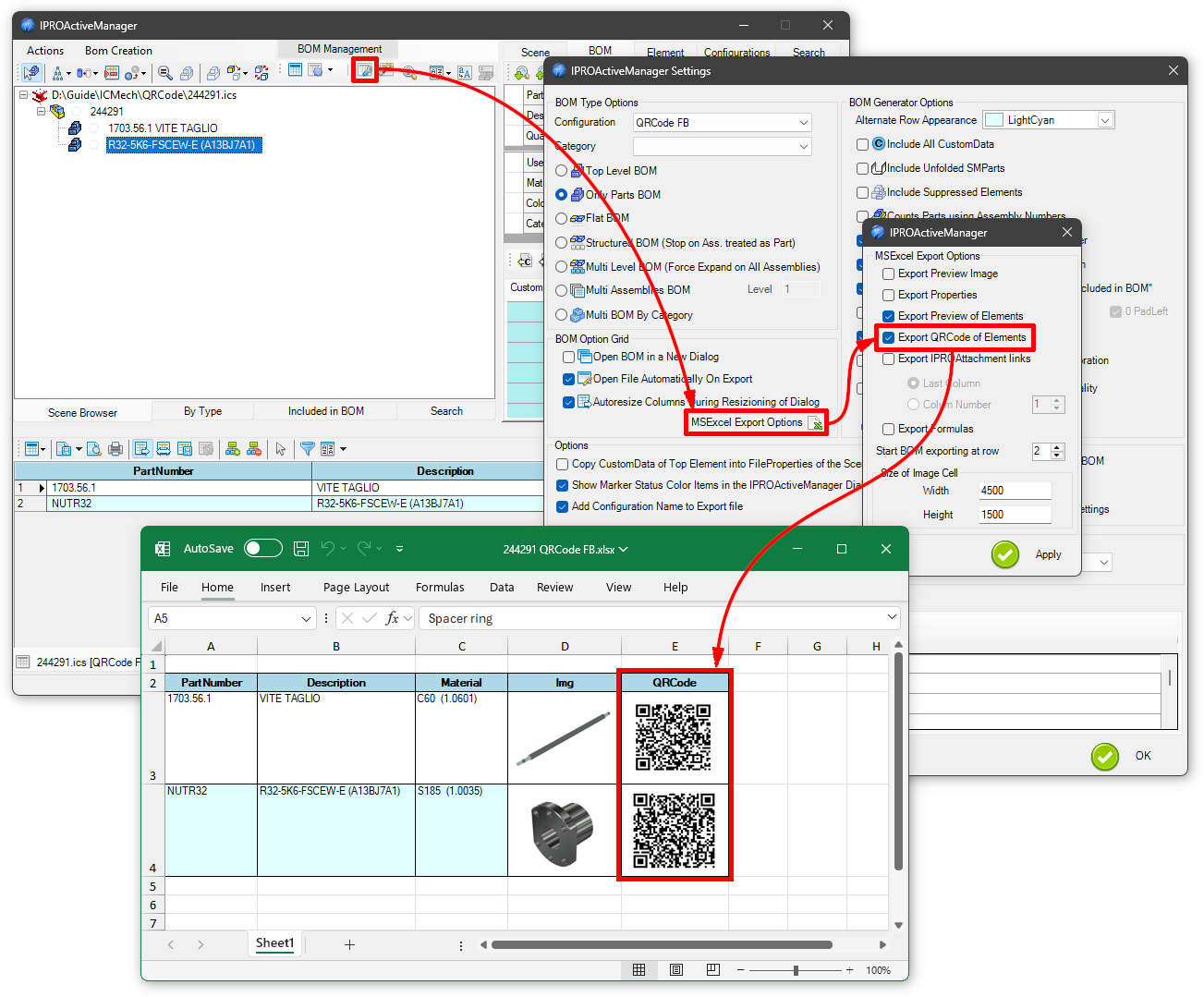
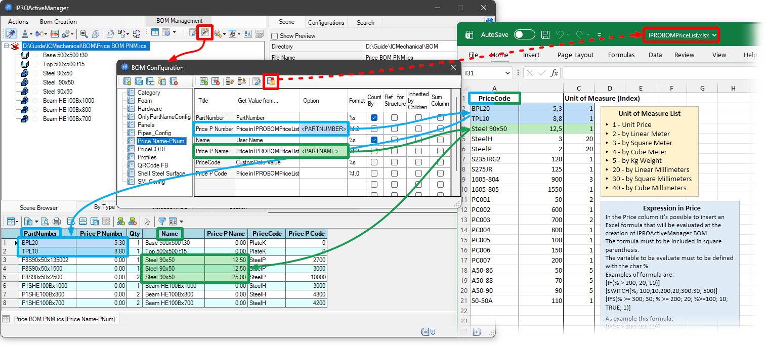


 For a detailed explanation see


 The Split IntelliShapes makes the reverse action. Select the intellishapes of a part that you want to have as a stand alone part. Then drop the Split Intellishapes tool into the scene.
 The Triball on COG tool positioning the Triball on the centre of gravity to the part.
 The Sphere on COG create a little sphere part with name CenterOfGravity on the centre of gravity.
 With to the Suppress Manager it is possible to suppress and unsuppress parts and assemblies in a very fast way.
 It removes the AddOn from any selected element. The AddOn is the intelligence added by ICMechanical to Screws, Steels and all other components included in ICMechanical.
 The Export unfolded part tool is a very convenient command for exporting sheets metal part to dxf or dwg files.
It is possible to export a single sheet metal, a selection of sheet metal or all the sheets metal of the scene.
The Export unfolded part tool is a very convenient command for exporting sheets metal part to dxf or dwg files.
It is possible to export a single sheet metal, a selection of sheet metal or all the sheets metal of the scene.


