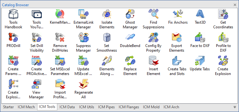
Subsections of Tools Catalog
Kernel Manager
 Dragging this command in the scene, we can change the modeling kernel of all parts in the scene, or alternatively only selected.

Click to show content from YouTube.
(read the service's privacy policy)
To change the kernel of all parts, select the item father (“Parasolid Parts” or “ACIS Parts”) and then click on the arrow above the list:
Violet Arrow -> changes from Parasolid to ACIS,
Blue Arrow <- change by ACIS to Parasolid.
To change the kernel only some parts, simply select it from the list and then click on the arrow to change the kernel.

With the buttons below parts lists, you can perform some operations:

- Suppress the selected parts
- Remove the suppression of selected parts
- Suppress all unselected parts
- Highlight the selected parts
External Link Manager
 The External Links Manager gives you the full control over all linked files in a scene.

Click to show content from YouTube.
(read the service's privacy policy)
The command has to be dragged to an empty area of the scene.


In dialog box there are three buttons with which you can either unlink a specified part or unlink all files in the entire scene (also with the possibility of unlink the children parts), or save with the name all parts.

Click to show content from YouTube.
(read the service's privacy policy)

The other four buttons allow you to: save the selected link file to another location (or rename the linked file), exchange the link with another file, open the linked file, save the selected part. These buttons are enabled only if you select an item in the tree view.
Note
When exchanging the link with another file, a dialog box allows you to choose how to replace the element.

In the bottom of the dialog, we have three tab to view the parts, those Linked and Not Linked

Also on the Not Linked tab is a tree view for selecting parts you want to save externally, there are also two controls: one for choosing whether to save all files in a single folder, and the other whether you want the exported part to be moved (based on the element’s own anchor) to the origin of the new file.
Note
 The new part number can also be assigned via the numbering tool, see here for how to use it.

The Element Selection menu is useful for quickly selecting elements (Select All, Select Assemblies, Select Parts, Select Sheet Metal Parts, Delete Selection) to export externally. It also contains an option to exclude IPROFasteners and an option to manage the Linked Mirrored elements, with the option of not Selecting or Unlinking them.
While the icons above the grid are respectively for:
- Fill the grid, to set by rules all new part names, part numbers and file names
- Search and Replace text, to rename in bulk: part name, part number, file name and folder.

And the tab Linked Files with a list of all files linked.

 In the tab Linked, the command Save all to New File, open a new dialog where you can manage the save of the linked parts, setting the new name and new part number, the destination folder and the file name.
This data can be changed individually for each part/assembly, selecting the relative cell within the grid and entering the new data, or by adjusting the controls placed on the top of the window you can automate some procedures.
Furthermore, if the source folder contains the 2D files of relating to linked parts, you can copy and update the links to the new file and the new folder.
All these options affect the behavior of the below grid:

Export All Files in the Same Folder:
When this option is active, the value inserted in the “New Path” column, will be copied for all the rows in the grid
Set FileName Equal to UserName:
When this option is active, the value inserted in the “New Name” column, will be copied in the “New File Name” column. In other words the exported file will have the FileName equal to the UserName of the element.
Set FileName Equal to PartNumber:
When this option is active, the value inserted in the “New PartNumber” column, will be copied in the “New File Name” column. In other words the exported file will have the FileName equal to the PartNumber of the element.
Set UserName Equal to PartNumber:
When this option is active, the value inserted in “New PartNumber”, will be copied in the “New Name” column.
Keep the Same FileName for Identical Links:
When this option is active, the value inserted in the “New Path” or “New FileName” columns, will be automatical copied in all the rows related to the links of the element. In other words, all the linked element will have the same folder and the same filename set automatically.
Keep the Same Data for Identical Links:
When this option is active, any change in the “New PartNumber” and “New Name”, will be automatically copied to all the linked elements
Save also current Scene:
When this option is active, also the main opened model will be inserted in the grid, and it will be possible to set any fields related to save options.
Copy 2D files:
This option does not affect the behavior of the grid. When this option is enabled, all ICD, EXB, and DWG files (whose filename is the same as the filename of the ICS file) in the source folder will be copied to the destination folder.
Reassociate 2D linked files:
This option doesn’t affect the behavior of the grid. When this option is active, at the end of the save/copy process, the reassociation process between 3D files and ICS files will be executed. This process runs automatically IronCAD in background and open, modify and save all the .icd files in the destination folder.
Caution
This process can require several time to be completed!
Furthermore, any error or prompt for “Corrupted Styles” fill put in pause the process, waiting the input from the user.
Copy All Other Files in Scene Folder:
This option doesn’t affect the behavior of the grid. This option is active when is set the “Save Also current Scene” option. When this option is active, all the files (e.g. Pdf, Word, Excel, DXF) in the source folder, will be copied to the destination folder.
 Also, with the Search and Replace button you can rename in bulk: New PartName, New PartNumber, New FileName and New Folder.

Isolate Elements
 The Isolate Elements tool manages the visibility of the elements of your project. It works in two modes, for StatusColor/Category or via dialog.

Click to show content from YouTube.
(read the service's privacy policy)
Operativity
- with the left mouse button:
- Drag in the scene with the left mouse button, the dialog box opens to select the elements according to the StatusColor or Category.

- Dialog box, with the right mouse button:
- Drag in the scene with the right mouse button, opens the dialog box to manage the saved states (or the interactive stored states).
- Here you can add, rename or remove states; add or remove items from a saved state, save or update camera orientation.
- To activate a status double-click on the name.


Click to show content from YouTube.
(read the service's privacy policy)
Ghost Manager

The Ghost Manager tool manages the visibility of the elements of your project.
It works in two modes, for StatusColor/Category or via dialogue.
Operativity
- with the left mouse button:
- Drag in the scene with the left mouse button, the dialog box opens to select the elements according to the StatusColor or Category.

- with the right mouse button:
- Drag in the scene with the right mouse button, opens the dialog box to manage the ghost saved states (or the interactive stored states).
- Here you can add, rename or remove ghost states; add or remove items from a saved state, save or update camera orientation.
- To activate a ghost status double-click on the name.

Find Suppressions

Dragging the command in the scene, a window appears with a list of parts/assemblies suppressed in the active scene, useful for finding all suppressed parts in a large assembly.

Click to show content from YouTube.
(read the service's privacy policy)
The buttons at the top of the dialog, allow to:
- highlight the selected items in the scene,
- unsuppress the selected items,
- suppress the selected items,
- delete the selected items.

Fix Anchors

This tool allows you to reset all of the anchors of elements of the scene (or active selection) in fixed mode (disallow drag).
If you want to fix also the anchors of intellishapes, drag the command in the scene with the right mouse button.

Click to show content from YouTube.
(read the service's privacy policy)


Text 3D
 This tool can create a 3D text part or 2D profile with all fonts avaible in the system.

Click to show content from YouTube.
(read the service's privacy policy)

If you drag on an existing part, you can also choose to create a cutting or extrusion, and you can get value to write the text from: PartNumber, Description, CustomData or Parameters.

On the left side of the dialog box there are buttons to choose font, size and styles; below them is the area where you write text.

While in the right part of the dialogue there are two zones, the first to define the Shape (part, intellishape or 2d profile), if you want to create a shape for each letter, whether to use the BSpline for the curves and the level of facet; the second to define the SizeBox of the text, the aspect lock and the alignment for the multiline.
For edit the text and values, right clic on intellishape and select Add-on Properties…
This is an example of the features available.

Get Coordinates
 Get coordinates, returns the coordinates of the points selected in the scene.

Click to show content from YouTube.
(read the service's privacy policy)
Drag each time the command to the desired point, the window will be increased the list of selected points.
Tip for detecting the coordinates of multiple objects
If you drop the tool in to the scene with an active selection and hold down the Shift key, all selected elements will immediately be transferred to the grid.

Click to show content from YouTube.
(read the service's privacy policy)

In the top of the dialog are icons for:
- delete a line
- export the list to Excel
- export the list to DXF file
- display global coordinates
- display local coordinates
- display coordinate from the anchor of the element
- display an arrow pointing to the selected point

Tip for detecting COG coordinates
Furthermore, when dragging while holding down the right mouse button, the COG coordinates of the element on which the tool is released are detected.
When releasing the tool on a sphere, the center point of the sphere is always calculated, rather than the point on the outer surface.

Click to show content from YouTube.
(read the service's privacy policy)
Info
When exporting to DXF, you can set the graphic characteristics by editing the
DXFTemplate.dxf fileThis is a standard DXF file which can be edited for the client’s purpose; it is used as a template to export the coordinates (obtained from the model) in DXF.
It is located in the ..\Drawing folder in the Templates folder that you set up in the General tab.
ProDrill

PRODrill tool, get every IntelliShapes named Drill (e.g. HWDrill, DrillHERE…), and it use it to “drill” every parts that has an interference with the HWDrill IntelliShape.

Click to show content from YouTube.
(read the service's privacy policy)

Operativity
- Drop the tool into the scene to apply the drill cuts for all parts.
- Select the assembly first, then release the tool into the scene to apply drill cuts only to the parts in the assembly.

ProDrill Naming Rules
- Part whose names starts or end with
_ are not drilled. - HWDrill element that contains the char
+ drills also element described at point 1. - HWDrill that contains
#1 in the name, drills only elements that are in the same assembly. - HWDrill that contains
#2 in the name, drills only element that are in different assembly. - HWDrill whose name start with
@ , don’t drill. - HWDrill whose name start with
# or contain _NS_ , drills elements and remain visible itself.
Note
If there is a mix of ACIS and Parasolid parts in a scene, the drilling operation will be slower.
Tip
You can use a Kernel Manager tool to recognize and convert all parts in Parasolid
Visibility ProDrill

This tool shows/hides all ProDrill features in all parts of the scene.
Operativity
- Drop it in the scene with the left button to show all the HWDrill.
- Drop it in the scene with the right button to hide all the HWDrill.

Remove Drill Holes

This tool removes all features of Drill holes in all parts of the scene, drop it into the scene to run it.

Click to show content from YouTube.
(read the service's privacy policy)
Suppress Manager

The SuppressManager tool allows you to Suppress (Unsuppress, Select and Delete) Parts, Hole and IntelliShapes based on various criteria such as Status Color, Category,Dimensions, Weight, Volume and Color.
Also the tool, allows you to create Configurations from the selection results.
Drag the command to the scene to activate, the dialog is divided into five tabs:
By Status Color
Search parts based on the Status Color,
It allows you to create a Configuration from the result of the selection.

By Category
Search parts based on the Category,
It allows you to create a Configuration from the result of the selection.

Parts
Search parts based on the size (or Based equivalent Volume), you can click on the cube with the arrows to detect the dimensions of the part selected in the scene.
It allows to:
- Suppress (Unsuppress, Select or Delete) smaller or larger parts of the stated values.
- Suppress or Unsuppress the Fasteners.
- Suppress or Unsuppress the Holes.
- Create a Configuration from the result of the selection.


Click to show content from YouTube.
(read the service's privacy policy)
Weight
Search parts based on a weight range.
It allows to Suppress (Unsuppress, Select or Delete) parts included or not included of the stated values.
It allows you to create a Configuration from the result of the selection.

Holes
Search holes (and the H IntelliShapes) based on the size (or Based equivalent Volume), you can click on the cube with the arrows to detect the dimensions of the part selected in the scene.
It allows to Suppress (Unsuppress, Select or Delete) smaller or larger holes of the stated values.
It allows you to Suppress All Holes.
It allows you to Unsuppress All Holes.


Click to show content from YouTube.
(read the service's privacy policy)
IntelliShapes
Search IntelliShapes based on the size (or Based equivalent Volume), you can click on the cube with the arrows to detect the dimensions of the part selected in the scene.
It allows to Suppress (Unsuppress, Select or Delete) smaller or larger IntelliShapes of the stated values.
It allows you to exclude from the search Blends, Chamfers and Drafts

Color
Search for parts by color, you can click on the color preview to select the color of the selected part in the scene.
It allows to suppress (Unsuppress, select or delete) equal or different parts with the indicated values (R, G, B and tolerance).
It allows you to create a Configuration from the result of the selection.


Click to show content from YouTube.
(read the service's privacy policy)
Set Smoothness
 This tool let you setting the Surface smoothness for all parts of the scene (or active selection), drag in scene and enter a value to specify surface smoothness of facets.


Difference between smoothness 10 and 50


Click to show content from YouTube.
(read the service's privacy policy)
Double Bend
 The Bouble Bend Tools is similar to Add Curved Stock in Sheet Metal catalog, the difference is that this tool add an parametric double bend, so you just have to enter the required values for add it at existing sheet metal.

For edit the values, right clic on intellishape and select Modify DoubleBend Parameters…
Double Bend example:


Click to show content from YouTube.
(read the service's privacy policy)
Config by Property

The Config by Property tool allows you to create Configurations based on certain Custom Data present in the elements of the current scene.
The dialog box is divided into three parts, the upper one there are icons for deleting, adding or removing the custom search rules, an icon to save the search presets, and a combo box to choose presets saved; in the middle, the grid with the customdata to search inside the scene, and at the bottom a text field to specify the name to be assigned to the configuration.


Click to show content from YouTube.
(read the service's privacy policy)
Export Elements

This tool allow to export a part or assembly to multiple formats at once.
Drag the tool onto the part (or into the scene, to export selected parts or assembly) and select the files formats.
The left side of dialog allows you to select the file formats to be exported, while the individual tabs set the options for the chosen formats.

At the bottom of the dialog box, you choose how to construct the file name and destination folder.
Export selected parts to separate files
If you want to export each part to a separate file, you must first select the parts and then drop the tool into the scene, a file will be created for each selected part.

Click to show content from YouTube.
(read the service's privacy policy)
Face to DXF
 This tool allow to export a face of part to a DWG/DXF file.

Click to show content from YouTube.
(read the service's privacy policy)
Operativity
- Drop the tool on to the face of the part with the left button, select the destination folder and the dwg/dxf format.
(the file name is the same as the part name)

- Drop the tool on the part face with the right button to open the dialog where you can choose options:
- Select Faces
- you can export an additional 2D sketch shape
- with hold the Shift key, add or subtract other faces
- select all parallel faces to the first choice
- select all coplanar faces to the first choice
- Settings
- options for the file name, if it is a SheetMetal part and how to write the data in dxf.

Note

We suggest to set the Export BSpline as Arcs, only in the case that it’s required by the CNC system. In all other cases, keeping the Export BSpline as Arcs unchecked will ensure that the geometry will be exported correctly.
Please verify the exported file before to deliver it, in the case that you check the Export BSpline as Arcs option.
After saving the file the result will be shown. (If you check “Execute IPROCadViewer after export” they will be opened in the CAD viewer ).


Click to show content from YouTube.
(read the service's privacy policy)
The settings and info to be written to the dxf file are also found in the IPROSettings dialog.
Tip
You can set the default parameters on Utils tab in global settings Configuration.And you can set the Templates folder on General tabThese are the templates used by the application:BendNames.iniThis file contains the Label name variables for upward and downward Bend.BendStyles.iniThis file contains the variables for setting styles for Layers, Colors and Lines.ExportFaceDimStyle.iniThis file contains some DXF variables that you can set. As example, it’s possible to change the DecimalPlace, the TextHeight, the TextAlignement and other variables related to DXF. This file is used when you export directly the parts to the DXF.UnfoldDimStyle.iniThis file is similar to the previous and it’s used when you export the parts using an icd fileUnfoldTemplateEmpty.icdIs the template used to export unfolded parts using the icd fileDXFTemplate.dxfIs used by the Get Coordinates tool. This is a standard DXF file that can be modified for the customer purposed. We use it when the coordinates get from the model are to be exported in DXF.
Profile to DXF
 This tool allow to export a section of intellishape to a DWG/DXF file.

Click to show content from YouTube.
(read the service's privacy policy)
Operativity
Drop the tool onto the intellishape of the part, select the destination folder and the dwg/dxf format.
(the dxf file name is set with the part name)

After saving the file will be shown the result.

Click to show content from YouTube.
(read the service's privacy policy)
The settings and info to be written to the dxf file are also found in the IPROSettings dialog.

Create Params by Excel
 This tool allows you to import parameters from an MS Excel sheet and assign them to the part in order to drive it.

Click to show content from YouTube.
(read the service's privacy policy)
Operativity
- Drop the tool on the part to which you want to assign the parameters, choose the cells of the parameters and their values.

Create ProActive Parts

PROActiveParts is a powerful tool useful to manage parametrical parts. PROActiveParts allow you to set and incapsulate into a parametrical part all the values related to the parameters. These values are indexed by the PartNumber. Furthermore also CustomValues and a Preview Picture can be set and stored inside the parametrical part.

Click to show content from YouTube.
(read the service's privacy policy)
When a parametrical part has been transformed to a PROActivePart, the user can change it double cliking on it (or right click and choose Add-on Properties).
How to create and manage PROActiveParts
In order to create a PROActivePart, you have to create a parametrical part.
Here is a Parameter Table related to a simple parametrical part:

When it will be transformed in PROActivePart, all the parameter values owned by the Part D1, d, Dm, L and T will be managed by ICMechanical.
How to create PROActiveParts
To start the PROActivePart tool, drag the “Create PROActive Part” item from the Tools catalog, and drop it over the parametrical part. In alternative, you can select before the part, then drag and drop the item in the scene.
This dialog will be displayed:
 How you can see, the columns of the grid in the dialog are PartNumber, Description and the names of the parameters defined in the part (only those contained in the part are shown, and only the free ones, i.e. without expressions that bind them to others). At this point the user can fill the grid with all the values related to parameters, or he can import them from an external MSExcel file.
Before to evaluate the import/export functionalities, we will describe the commands available on the dialog box:
 This group of buttons allow the user to create, rename or delete the groups grid.
This allows parameters to be managed in different grids (called Groups); which will be shown in the part selection dialog.

 This group of buttons allow the user to move, insert or delete the rows of the grid.
 This group of buttons are used to add, remove, rename and update a Custom column in the grid, add color, and load or add new parameters.
Custom columns are used to set values that will be transferred to the CustomData of part. User can add and delete these columns, but he cannot add or delete columns related to parameters or BOM Information.
 This button adds a column to define color; it is useful for associating a color to be applied to the element related to each record.
 This button shows a dialog with the names of the parameters associated with the part, you can then add them all to the grid, or just the selected ones.
How you can see, every column has an icon that describes the type of data.

 This option is used to define in what Unit of Measure are to be considered the parameter values inserted.
 This text box is used to assign a name at the ProActive Dialog, and will be visible at the top of the dialog.

 This option is used to select the Material for the part.
 The buttons included in this toolbar are used to create, select an existing image and preview the Picture to be associated to the PROActivePart.
 These buttons are used to create a 2D drawing (based on a chosen icd model) for each row of the table and export them to pdf or dwg files separately.
 These buttons are used to import or export the data contained in the grid. Using the import functionality you can import all the parameter and custom values from an existing MSExcel file.
As example, here is a valid MSExcel table that you can import:

How you can see, the first row contains all the Names related to the columns. During the import, every column name will be evaluated and associate to the correspondent parameter name. Every column that will not match with a parameter, will be managed as Custom Data. In the above example, the columns “Supplier” and “Note” will be Custom Data.
After the import of the above MSExcel file, the dialog will similar to this image:

The user can still edit any value, add or remove any Custom column and move change the order of the rows. If the user double click on the Row Counter, the values of the parameters in the row will be transferred to the parameters in the part.
When the user clicks on Apply or on the OK button all the information on the grid, and the Preview image will be elaborated and stored inside the part. In other words the part has become a PROActivePart.
At the bottom of the dialog box are two tabs for management:
In addition, one or more cells in an Excel file can be linked to the fields.

The user can also create complex expressions (based on the data extracted from the part) to assign to variables or use to fill in the properties.

This button is a simple help to explain the use of tags in cells:

@ means any numeric parameter value can be entered manually, insert a value after @, it will be use as default.[...] means that the user can choose from a series of defined values, the values must be inserted between the characters [ ] and must be separated by a semicolon ;<...> means that the parameter value can be entered manually between a min and max value, the values must be inserted between the characters < > and must be separated by a semicolon ;

The last button activates automatic sizing of the grid columns. If the user clicks it, the columns fix the current size.

Operativity
When the user double click on a PROActivePart, or when he drop it inside a scene, this dialog will be displayed:

Using the PartNumber option (and/or other group options if present), the user can select the type of part to use, and all the parameters and customs will be filled with the right values.
Tip
You can change which data to use as a search, in the data edit container grid, simply drag the column you want to use to the first position.
Tip
If you want to create the PartNumber or Description with some grid data insert the parameter name between < > while if you want to add a CustomData in between <@ >
| PartNumber | Description | D1 | d | Dm | L | T |
|---|
pin <Dm> <L> | flange bushes <DM>x<L> th=<T> | 57 | 44 | 46 | 32 | 3.3 |
| will be returns as: | will be returns as: | | | | | |
| pin 4632 | flange bushes 46x32 th=3.3 | 57 | 44 | 46 | 32 | 3.3 |
 Also, if you click the Data button, the dialog will expand and you will see the grid containing all the data and you can select and apply the values by double clicking on the grid:

Note
 This button (displayed only if excel data values are used) allows you to update the parameters associated with an MS Excel data file.
 In addition, if the user clicks on the Settings … button, the On Drop dialog will be opened and you can choose how to display the ActiveParts dialog box; the choices are:
- Always
- Only when you release in the background
- Never

Edit data
 This button allows you to position all the elements contained in the grid by applying all the values in succession, when you click, a dialog appears to define how to position the elements in the scene.

 This button activates automatic sizing of the grid columns. If the user clicks it, the columns fix the current size.
 This button allow you the edit the data contained in the grid. If the user click it, the dialog described at the beginning of this page will be displayed.
 It is also possible to hide some columns; this operation also hides the values in the dialog box.
Set MsExcel Parameters
 It allows you to assign the value of cells of Excel files to the parameters of a part.

Operativity
- Drop the tool on the part,
- A dialog box appears with the available fields (parameters), click on the Folder or File cell and select the Excel file,
- A new dialog box appears showing the Excel sheets,
- Select the cell you want to assign to the parameter and confirm.
- Repeat for each field you want to assign.
 At the end of the operation close the dialog box, an icon with the
 fx symbol appears near the anchor to indicate that an excel file is associated with the part.

For Show params
Right click on the part and choose Show Parameters Controlled by MSExcel
For Update params
Right click on the part and choose Update Parameters Controlled by MSExcel or use the tool Update MSExcel Parameters.
For Edit MSExcel file
Right click on the part and choose Open MSExcel file that controls Parameters… to open the file directly.
Tip
If the Excel file and the IronCAD file are not in the same directory, add (at the bottom of the dialog) the folders to search for Excel files.
Note
To remove the association with the Excel file, right click on the part choose Show Parameters Controlled by MSExcel and clear the grid, even just the Folder column.
Update MsExcel Parameters
 This tool allows you to update parts that have parameters controlled by Excel file cells (assigned with Create Params by Excel and Set MsExcel Parameters)
Operativity
Drop in the scene to update.
Elements along 3D Path

With this tool you can position an element (part, assembly or intellishape) along a 3D curve or 2D sketch.

Click to show content from YouTube.
(read the service's privacy policy)
Operativity
- Select the element and the path (curve or sketch),
- Drop the tool into the scene.
In the dialog, set the number of copies, the distance (or even distribution) and if necessary the offset.

It is also possible to change the orientation in tangency along the curve with respect to the X and Z axes of the element anchor (each click on the arrow rotates the object in steps of 90 ° with respect to the chosen axis).
The positioning of the element along the path is done with respect to its anchor, as well as rotations.
Replace Element

This tool allows you to replace one or more elements with another from an external file or present in the same scene.

Click to show content from YouTube.
(read the service's privacy policy)
From external file
Operativity
- Select the element (part or assembly) to be replaced and then drop the tool into the scene,
- select the file you want to insert,
In the dialog box displayed you can set how to replace elements:

- all linked elements,
- or only the selected element.
Elements that have the same PartNumber:
- all the elements,
- only elements in the same parent (assembly).
Elements that have the same UserNumber:
- all the elements,
- only elements in the same parent (assembly).
The inserted element will be automatically linked to the original, if you don’t want it, you can unlink it after replacement.
Replace in place
If you want to use the tool to replace elements with an element present in the active scene, release the tool with the right mouse button,

the dialog box is similar to the previous one but allows you to choose the element to be used for the replacement directly in the active file.
Operativity
- Select the element (part or assembly) to be replaced and then drop the tool into the scene with the right mouse button,
- set the element replacement mode,
- select the element that will replace the previous ones.
Tip
If you want, you can keep the element linked to the replaced elements (works only in the same file, does not link a part in an external file).

Click to show content from YouTube.
(read the service's privacy policy)
Insert Element

With this tool you can insert an element from your library of files into the scene.

Click to show content from YouTube.
(read the service's privacy policy)

Operativity
- Drop the tool into the scene.
In the dialog box, you can, in the first combo box, select the User Library folder that contains the element you want to insert,

then in the second combo box, select the item you want to insert.

Tip
If you want to insert the element as linked, select the option above.
Note
The User Libray folder is normally set in ..\ICMechanical\UserLibrary but you can set it wherever you want, use the IPROSetting tool to do it.
Create Tabs and Slots

 This tool allows you to add tabs and slots to both sheet metal and innovative parts.

Click to show content from YouTube.
(read the service's privacy policy)
Operativity
- Drop the tool on the edge you want to add the tabs to.
In the dialog box you can select type and set the dimensions:
in the first combo box, select the type of tab you want to add,

See here for how to add your Tab.
Placement
 Here you can choose the type of placement between:
- Evenly Spaced - choise of copies and distance calculated automatically
- Distance Spaced - choise of distance copies auto
- Fixed Spaced - choise of distance and copies
- Center Spaced - choise of distance and copies from centre
- Edge Length - equal tu the edge
- Custom - choice of distance between each tab
- Custom & Length - choice of the distance between each tab and also of the length of each tab
The distance and the number of tabs vary according to the choice of placement.
Offset
 In this section you can set the starting and ending offset, the icon on the right allows you to swap the start and end.
Dimensions Tab
 Here you can set all the dimensions based on the chosen tab (so some boxes may be inactive).
- Length of the tab.
- Height of the tab.
- Reduction of the tab height (but not of the slot).
- Round/Chamfer size.
- Radius of the hole at the base.
Slot Type and size

In this section, you chose type and set the clearance spaces around the tabs, these are the dimensions that will create the slot hole on the opposite element.
 The padlock on the right allows you to enter values that are all the same.
(The size of the cut boundary is represented with a semi-transparent yellow shape)
Edit Remove and Update Tabs
To change tab settings, select an IntelliShape-level tab, right-click IntelliShape and select Edit Tabs.
Similarly, if you want to delete all the tabs on the border, right-click IntelliShape and choose Remove Tabs.

If the element has changed size (thickness or dimension), you can update all tabs in the part, right click on the part and choose Update Tabs

Click to show content from YouTube.
(read the service's privacy policy)
How to create a new Tab
In order to create your tabs and slots, the models must be parametric, and be saved in the folder of the library.
Here are two example of Tab and Slot:
Tab1.ics is a part with a one parametric section:
The IntelliShape named Tab creates the tabs on the element on which you drop it, and must contain these parameters:

- L - corresponds to Length of the Tab
- H - corresponds to Height of the Tab
- R - corresponds to Round or Chamfer if present
- RH - corresponds to base Hole Radius if present
Thickness isn’t present because it’s calculated from the element on which the command was dragged.
Slot3.ics is a part with a one parametric section:
The IntelliShape named SMDrill creates slots on the neighboring element on which the tab is released, and contain these parameters:

- L - corresponds to Length of the Tab
- TH - corresponds to the tolerance to be added to the height
- TL - corresponds to the tolerance to be added to the length
- RC - corresponds to base Hole Radius if present
W = Thickness it’s calculated from the element on which the command was dragged.
Note
The Libray folder is normally set in ..\ICMechanical\Library\Tabs and ..Library\Slots but you can set it wherever you want, use the IPROSetting tool to do it.
Tip
If you want a preview to appear in the combo box, you need to add a .jpg file with the same name as the .ics file, this is an example:

Update Tabs

Update all elements with Tabs&Slots.

Click to show content from YouTube.
(read the service's privacy policy)
Operativity
- to update all elements in the scene, drop the tool into the scene.
- to update only one element, drop the tool on the element.
- to update only the elements of a selection, first select the elements, then drop the tool into the scene.
Create Explosion


With this command it is possible to create different types of exploded views, which are saved in the configurations.

Click to show content from YouTube.
(read the service's privacy policy)
Operativity
- Drop the tool into the scene to create an exploded view of all elements.
- To create an exploded view of only the selected elements, first select the elements, then drop the tool into the scene.
- Now drag the slider or type the explosion percentage, and dynamically see the result.
Options
The icons at the top allow you to:

- Set a new selection to explode:
- useful for redefining the elements to explode from now on.
- Remove items from selection…
- Add items to the selection…
- Show active selection:
- useful for seeing the elements that are subject to the explosion.
- Show TriBall in the center of the explosion:
- useful for redefining the center point from which to start the explosion.
You can explode elements from:

- the center of the footprint of all elements
- following the Z direction of each element (Z is the long green whisker on the Anchor)
- following the negative Z direction of each element
Explode Assembly to treat as Part: if you check this box, you also explode the elements in these assemblies.

Configuration Name: set a name to the configuration to assign to this explosion.

Create Explosion Lines


Tool to create, show, suppress or delete explode lines of an Exploded configuration.
The lines can be continuous or dashed.
Operativity
- Drop the tool into the scene and set the lines.
Views Manager


Useful tool for saves and restores camera status, active configuration and item visibility. This tool also stores the suppression status of the elements. It is a kind of “enhanced” Camera and Configuration Save, with a preview image and some text fields to use for documentation. All this information (images and text) can be exported to an MSExcel or MSWord document.
Operativity
- Drop the tool into scene,
- Adjust the view, hide or suppress unnecessary elements , or select the configuration and then click Save Current View/Configuration,
- Add view title, description and note,
- Repeat step 2 and 3,
- Export to MsWord or MsExcel,
- or save all images in one folder.

The buttons are used for:
- Move the saved view Before or After,
- Save the current view,
- Update and save the selected view,
- Delete the current view,
- Set the size of the image to be saved,
- Export the History of Views,
- Export all images in one folder.

Click to show content from YouTube.
(read the service's privacy policy)

In the left side of dialog there are a buttons for:
- set the target camera,
- use TriBall for set target point,
- set the view orientation with Z axis,
- set angle of rotation view,
- buttons for rotation by angle,
- set step of pan view,
- buttons for move view by step.

Click to show content from YouTube.
(read the service's privacy policy)
Info
You can use IPROCamera Manager - Place IPROCamera to create, place and manage cameras.
Import Profiles from Scanner

Import and manage points from the scanner.
Operativity
- Drop the tool into scene, and choose file to import:

- automatically generates profiles,

- and creates an extrusion or loft from a selection of profiles.


Click to show content from YouTube.
(read the service's privacy policy)
Regenerate Scene

Similar to the Regenerate tool in Tools/Operations Ribbon, but in this case it regenerates all elements of the 3D scene without making any selection.
Operativity
- Drop the tool into scene.