Create Tabs and Slots

 This tool allows you to add tabs and slots to both sheet metal and innovative parts.

Operativity
- Drop the tool on the edge you want to add the tabs to.
In the dialog box you can select type and set the dimensions:
in the first combo box, select the type of tab you want to add,

See here for how to add your Tab.
Placement
 Here you can choose the type of placement between:
- Evenly Spaced - choise of copies and distance calculated automatically
- Distance Spaced - choise of distance copies auto
- Fixed Spaced - choise of distance and copies
- Center Spaced - choise of distance and copies from centre
- Edge Length - equal tu the edge
- Custom - choice of distance between each tab
- Custom & Length - choice of the distance between each tab and also of the length of each tab
The distance and the number of tabs vary according to the choice of placement.
Offset
 In this section you can set the starting and ending offset, the icon on the right allows you to swap the start and end.
Dimensions Tab
 Here you can set all the dimensions based on the chosen tab (so some boxes may be inactive).
- Length of the tab.
- Height of the tab.
- Reduction of the tab height (but not of the slot).
- Round/Chamfer size.
- Radius of the hole at the base.
Slot Type and size

In this section, you chose type and set the clearance spaces around the tabs, these are the dimensions that will create the slot hole on the opposite element.
 The padlock on the right allows you to enter values that are all the same.
(The size of the cut boundary is represented with a semi-transparent yellow shape)
Edit Remove and Update Tabs
To change tab settings, select an IntelliShape-level tab, right-click IntelliShape and select Edit Tabs.
Similarly, if you want to delete all the tabs on the border, right-click IntelliShape and choose Remove Tabs.

If the element has changed size (thickness or dimension), you can update all tabs in the part, right click on the part and choose Update Tabs

How to create a new Tab
In order to create your tabs and slots, the models must be parametric, and be saved in the folder of the library.
Here are two example of Tab and Slot:
Tab1.ics is a part with a one parametric section:
The IntelliShape named Tab creates the tabs on the element on which you drop it, and must contain these parameters:

- L - corresponds to Length of the Tab
- H - corresponds to Height of the Tab
- R - corresponds to Round or Chamfer if present
- RH - corresponds to base Hole Radius if present
Thickness isn’t present because it’s calculated from the element on which the command was dragged.
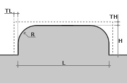
Slot3.ics is a part with a one parametric section:
The IntelliShape named SMDrill creates slots on the neighboring element on which the tab is released, and contain these parameters:

- L - corresponds to Length of the Tab
- TH - corresponds to the tolerance to be added to the height
- TL - corresponds to the tolerance to be added to the length
- RC - corresponds to base Hole Radius if present
W = Thickness it’s calculated from the element on which the command was dragged.
Note
The Libray folder is normally set in ..\ICMechanical\Library\Tabs and ..Library\Slots but you can set it wherever you want, use the IPROSetting tool to do it.
Tip
If you want a preview to appear in the combo box, you need to add a .jpg file with the same name as the .ics file, this is an example: