Create Steel Cap / Tube Cap


The Create Steel Cap and Create Tube Cap tools allow the automatic creation of end plates and caps directly on structural steel profiles.
To create a cap, drag the command onto the desired end of the steel profile (start or end of the member). The cap is automatically generated according to the selected parameters and profile dimensions.

Positioning
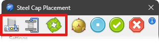 You can use these icons to control the cap’s position:
- Reverse the extrusion direction
- Add another identical cap on the opposite side
- Rotate the cap 90° with each click
Settings

This box allows you to save the component’s current settings. This enables you to quickly retrieve them in future sessions. The buttons here allow you to save, remove, or apply the saved settings.
Profile Type
Using the profile type combobox it is possible to select the plate corner style: Sharp corners, Chamfered corners, Filled corners. Furtemore, the LxH dimensions of the steel’s overall sizes are displayed on the right.

Parameters
The following parameters define the stiffener geometry:

- Th - Plate thickness
- D1 / D2 / D3 / D4 - Distances from the steel profile edges to the cap boundaries - (The lock icon is used to set the same value)
- Rs - Corner radius or chamfer value, depending on the selected profile type
Holes
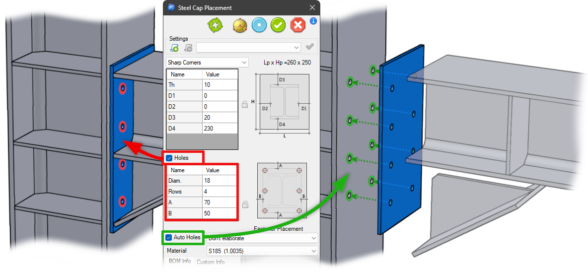
 By enabling the Holes option it is possible to automatically create hole patterns on the cap plate.
Available parameters include:
By enabling the Holes option it is possible to automatically create hole patterns on the cap plate.
Available parameters include:
- Diam. - Hole diameter
- Rows - Number of hole rows
- A & B - Hole spacing distances - (The lock icon is used to set the same value)
Auto Holes and Fastener Placement
By enabling the Auto Holes option, you can automatically create the corresponding holes in the support element plate.
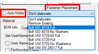 In addition, the drop-down menu under Fastener Placement allows you to add bolt groups.
The available options include:
- Do Nothing - take no action
- Remove Existing - if present, remove the bolt groups
Or you can choose which type of bolts you want to place
- Bolt…type…
Show how add custom Bolt type:
The bolt types you want to use must be saved in the folder
..\Library\SteelsLib\Fasteners
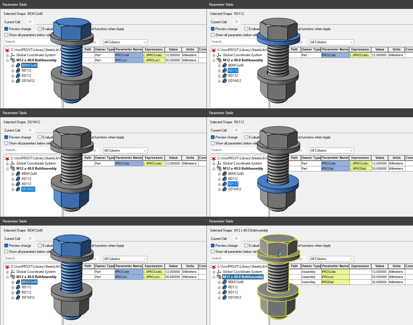
- In a new scene, add a Fasteners Assembly
- Select the bolt type, washer, and nut
- In the parameter table, add these parameters to the assembly:
- IPROCode - sets the component size
- IPROLen - sets the length of the bolt shank
- IPRODist - calculates the thickness of the plates used to position the washer or nut
and all components:
- IPROCode
only to bolt:
- IPROLen
to second washer (or if non here to the nut)
- IPRODist
and referred all to the assembly parameters
- Save the file with a meaningful name, e.g., Bolt ISO 4018-No Washers.ics in:
..\Library\SteelsLib\Fasteners
- Library
- Pipes
- Profiles
- RailingsXT
- SteelsLib
- Caps
- Ribs
- DataFiles
- Fasteners
- Bolt ISO 4018 - Full.ics
- Bolt ISO 4018 - No Washers.ics
- Bolt …..
- SteelStairs
- Tabs
Material
The material assigned to the stiffener can be selected directly from the dialog.

BOM Information
The bottom section of the dialog contains the items useful to set the information related to the component. The section is divided in two parts: BOM Information and Custom Information.
BOM Information section contains the same options of the other components, but there is this option more:
 User Name Prefix - This check button controls the enable state of the text item placed on the right. If this button is checked, any string placed in the text item will be used as prefix of the User Name.
Note
When the tool is positioned on one of the ISO and DIN steel types and moved accordingly, the part number prefix changes. Steel caps are categorized by their location: at the Base (prefix F), at the Top (prefix T), and at the End (prefix E). The options for Prefix Name and Prefix Part Number are filled automatically and correctly.
For a detailed explanation of the other items see BOM information