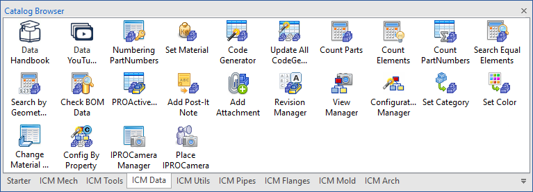
Subsections of Data Catalog
Numbering PartNumbers
 Element Numbering, allows you to assign an incremental code to an element or selection of elements, by setting a prefix for the project and the increments for the series, you can also assign a category.

Click to show content from YouTube.
(read the service's privacy policy)
The command generates, for each project, a report in Excel format that contains the list of codes assigned to the part/assembly and the
relative information (code, file name, element name, type, description,
material, date, user).
Tip
The directory path where is the file is defined in dialog ICMechSettings - Global Setting -> Numbering

Select one or more parts and drag the command to the scene.
In the dialog that appears you choose the project and the series (and possibly a category) to be assigned to the selection, the code will be shown in the bottom box and confirming will be applied to the part.
At the top of the dialog we find four icons for managing the numbering.


In the Projects tab you assign the project name and number, while in the Series tab you set the minimum starting number value, the length of the field, the fill character, the prefix and the postfix.
Info
If you want to define a persistent, generic counter that is not associated with any project, the Number Series name must begin with %, e.g., %Sequential Number A


Reserve Series Number & Reset Counter

In these dialogs you can reserve coding numbers, or you can assign a new initial value.

Edit Categories

From this dialog it is possible to manage the list of categories.
Set Material

With the command Set Material can apply a material to a part or a selection of parts or assembly.

Click to show content from YouTube.
(read the service's privacy policy)
Drag the command on the part to which you want to set the material.
If you want to assign the same material to a selection or an assembly, first select the parts or assembly and then drag the command to an empty area of the scene.

Note
The Set Material tool is used for all elements that are “generic” parts (no ICMech elements).For ICMech elements, (Steels, bolts, etc) use the material file defined in that tool, see Library Data Manager
In the window that appears you can select the material to be applied by selecting it from the drop-down menu Material name.

Also you can set the weight (clicking on the icon which appear) and in this case the density will be calculated accordingly.

If the selection is a assembly, you can set the material for all the parts of the assembly, while clicking on the Kilogram icon will show the current weight.

Edit Material Files
The Edit Material Data button opens the dialog box where you can manage the materials.

Here you can add or delete a material category, edit a material by assigning it a name and a density, and also set the graphic appearance by choosing the transparency, color and or texture, you a code and description, can also assign a Caxa hatch type and assigning.

Tip
The list of materials is stored in several files that you find in the folder ..\ICMechanical\Materials
You can also change in which directory you store the files, in DataFiles -> Material
Code Generator
 Code Generator allows you to automatically generate and assign UserName, PartNumber and Description according to variables related to the model, so that the edit of the model even the Name, PartNumber and Description will be updated to the new value.

Click to show content from YouTube.
(read the service's privacy policy)
In the upper left there are four icons to load and save a configuration, set the current rules as defaults and remove any predefined settings, just below four text fields in which to write the data generation rules, while on the left the buttons with the label, which when pressed show a preview of the assigned value.

at the bottom of dialog box, there are two tabs:
CustomData Tab, which defines the CustomData to add to the element and how to generate them.
- Name - name to be assign to the CustomData
- Expression - rule to define the value to be assigned to the CustomData
- Value - value generated by rule and placed in the CustomData
Example of custom data get from expressions.

Variables Tab, defines variables to be used to compose the User Name, PartName and Description.

- Variable - name to be assigned variable
- Get from - data from which to take the value
Variables in Column Get From:
| Variables Type: | returns: | option Name: |
|---|
| CustomData Value | value of the CustomData | the name of the CustomData contained in the element |
| Material Name | material name of the element | |
| User Name | name of the element | |
| Sizebox Height of Element | total height of the element | |
| Sizebox Length of Element | total length of the element | SM_Unfold returns the L dimension of the unfolded sheet metal |
| Sizebox Width of Element | total width of the element | SM_Unfold returns the W dimension of the unfolded sheet metal |
| Thickness of SheetMetal | thickness value of sheet metal | |
| Weight of Element | weight value of the element | type of measurement Kg g lb oz |
| Weight of Element in Water | weight value of the element in water | type of measurement Kg g lb oz |
| Parameter Value | parameter value | name of the Parameter contained in the element |
| Volume of Element | volume value of the element | |
| Shell Feature | thickness value of the shelled part | |
| Thickness of IPROSteel | thickness value of steels that have this property | |
| Code of SheetMetal | sheet metal code value | |
| Part Number | part number of the element | |
| Description | description of the element | |
| Sweep Path or Extrusion Section Length | value of the length of the guide curve (3D curve or 2D sketch) of the sweep | |
| 3D Curve Length | value of the length of the 3D curve | |
| Document Properties | file property value | name of the Properties contained in the file |
| Element Surface | surface value of all faces of the part | |
| Global Position X | X value of the absolute position | |
| Global Position Y | Y value of the absolute position | |
| Global Position Z | Z value of the absolute position | |
| Longest Value of Sizebox | the longest value (among L W H) of the sizebox | |
| Number of Items | number of linked elements (both internal and external) | |
| Quantity | quantity of the element | |
- Name - the possible name of the data if available
- ex. for Parameter Value, the name of the Parameter
- ex. for weight you can choose the type of measurement
Kg g lb oz - ex. for sizebox length and width,
SM_Unfold returns the L and W dimension of the unfolded sheet metal part
- Dec. - number of decimal to consider (If the Dec. value is negative, trailing zeros will be removed)
- Len. - length of the field (-1 undefined)
- Fill Chr - fill with this character (if Len.> 1)
- Value - value found by Get From
For edit the Code Generator, right clic on the part and select Open Codification dialog…
Example of construction of user name, part number and description.

Update all GenCode Parts

Updates all parts with Code Genator.
If in the project, there are many parts to the CodeGenerator, drag this tool on the scene and will update all.


Count Parts
 A simple tool to count all the parts of your project, drop it into the scene and here’s the result :-)


Click to show content from YouTube.
(read the service's privacy policy)
Tip
If you drag with the left button, it counts all parts in the scene.
If you drag with the right button, it counts only those that are not suppressed.
Count Elements

Tool to count all elements in the scene (total is shown in parentheses), grouping them by type, such as: Assemblies, Empty Assemblies, Parts, Structured Parts, Surface Parts, Reference Parts, Sheet Metal Parts, Facet Parts, 3D Curves, External Links, Fasteners, Steels (also these are divided by type and the total length is shown), Pipes and Flanges.
Drag and drop the command into the scene and here is the result.
By right-clicking on the group, you can Select, Suppress or Unsuppress them.

Count by PartNumber

This tool counts all the elements of the scene and writes in each part a custom data called “Quantity” with the total value based on the sum of the part number.
Drop it into the scene for execute.

Search Equal Elements
 This tool searches and counts all the elements in the scene have the same Name or PartNumber.

Click to show content from YouTube.
(read the service's privacy policy)
Operativity
- Select the element(s) whose quantity you want to know,
- drop the tool in the scene,
- choose whether you want to count the elements by Name or by PartNumber
- click on the lens icon to count the elements.

Search by Geometry Equality
 This tool searchs all parts that are geometrically equal, to a selected reference part.

Click to show content from YouTube.
(read the service's privacy policy)
Operativity
- Select the element whose equal ones you want to find,
- drop the tool in the scene,
- click the Lens icon to find and count all equal elements.
or:
- Drop the tool in the scene,
- select the element whose equal ones you want to find,
- click the Part icon to recognize the geometry of the element,
- click the Lens icon to find and count all equal elements.
The property values of the elements found are editable, and activating the “Keep Equal Column Value” control allows the values to be kept equal.

Check BOM Data
 This tool is used to check items that have the same shape but different bill of materials data, or that have different shapes but the same bill of materials data.

Click to show content from YouTube.
(read the service's privacy policy)
Operativity
- Drop the tool in the scene,
- check the mismatches found.
The property values of the elements found can be modified, so you can correct the values and, by clicking on the “Run DataCheck again” icon, you can check if any other discrepancies have been found.

ProActive Manager

ProActive Manager is a big piece of the ICMechanical, is a utility that quickly and easily manages the properties of the elements, such as Name, Description, Code, Material etc… It allows you to create BOMs in the 3D scene, you can create them easily and in many different ways with a lot of settings.
There is also Configurations management, Search functions and a number of small smart tools built in. With this tool you can work directly on the BOM in the 3D scene and add, delete and modify the Properties of parts and assemblies very quickly and easily!
Subsections of ProActive Manager
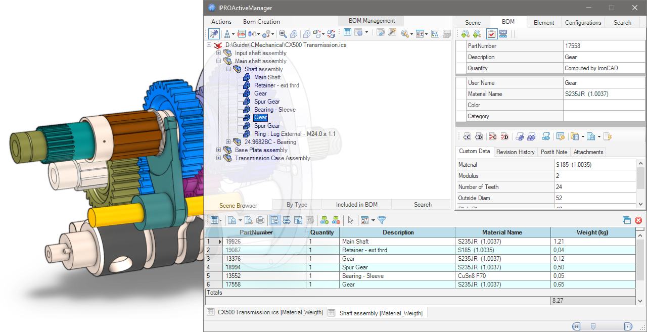
ProActive Manager Dialog


Drop the ProActive Manager icon from the Tool Catalog into the scene, or click the icon in the Add-ins tab, in the IC Mechanical group; this dialog will open.

In the Left Side scene management, here you can choose how to view the scene browser, in fact the icons in the upper part are used to turn on/off, suppress…While in the bottom edge there are four tabs, the first is the Scene Browser, the second By Type is a tree divided by type of elements grouped automatically into: assemblies, parts, sheetmetals, 3D curves, external links, fasteners and steels; the third tab Included in BOM separates the elements included or not included in the bill of material; finally, the fourth tab Serach containing the results of the search function.
see more here…
On the Right Side there are also here some tabs whose number changes according to what is selected in the browser on the left.There is the Scene tab which shows the properties of the open * .ics file. The BOM tab to manage the data of the bill; the Element tab which shows the geometric data of the elements. The Configuration tab that manages the configuration of the file and finally the Search tab, where you can search and manage searches for elements in the open file.
see more here…
In the Bottom Side of the dialog the Bill Of Materials is shown (normally it is hidden, to show it you have to create a BOM ).Above the BOM grid there are icons for Exporting the BOM, printing it and managing its display, while below, one or more BOM tabs, with the name of the selected file or assembly, and in square brackets which [BOM configuration name] was used to create it.
see more here…
To view the BOM you want, you need to create a configuration and set it in BOM settings to choose what to include, and how to format the different columns, etc.
Subsections of ProActive Manager Dialog
Left panel - Browser

Icons
In the upper left part of the dialog box, there are some icons to control the tree view display:

 Some icons appear in the TreeView to indicate that the elements contains particular information:Assembly Name in Bold Blue Font - it means it has AutoNaming
 - it means it has Attachments
 - it means it has Revisions
 - it means it has PostIt Note
 - it means it has Status Color
 - it means it is a linked file and
  the path.
Actions
 - Select in the Scene the selected TreeNodes
 - Update the TreeViews, Refresh, Expand and Collapse All
 - Select Element in BOM Grid (only active when there is a BOM grid)
 - Hide Selected Elements, Hide Unselected and Show All
 - Ghost Selected Elements, Ghost Unselected, UnGhost All
 - Zoom on Selected ItemEach click rotates the view by 90 degrees, but if the item is selected in the scene, the first click shows it in the browser and in the BOM tab
 - Set Trasparent All Other Parts
 - Suppress All Other Parts
 - Suppress/UnSuppress the Selection
 - Exchange Selection
 - Create new configuration (only active when use Suppress All Other Parts)
BOM Management
icons to manage the BOM:

 - Create BOM
 - BOM Settings
 - Open Settings Dialog…
 - Open BOM Configuration Manager…
Utils
and some utility icons:

 - Search by Properties
 The results will be shown in the Search tab (see bottom of this page)
 - Set TreeView Sort Option
 Sorts by PartName, Creation date, PartNumber or Category; the last option sets the new sorting to the SceneBrowser
 - Search and Replace Text inside elements
 - Rename Children Parts (active only when an assembly is selected)
Tabs
In the bottom edge there are four tabs:
Scene Browser
It is the same tree view as the scene

By Type
Is a treeview divided by type of elements grouped automatically into: assemblies, empty assemblies, parts, sheetmetals, 3D curves, external links, fasteners and steels; it is also possible - with the right click - to Suppress/Unsuppress all elements in the group.

Included in BOM
Shows the elements included in the BOM, or those not included or see them both (with the combobox below you can choose how to see them)

Search
This tab containing the results of the search function;
search for a multiple fields:

search for a Status filter:

or the result of Search by Properties.

Note
For how to set the search function see here .
Right panel - Properties

On the right side there are some tabs whose number changes according to what is selected in the browser on the left.
Scene
This tab shows the properties of the opened file (in the top grid), while in the bottom tab “Scene Properties” you can edit them or add new ones, if you want to always add the same properties in all scenes, see here.

BOM
In the BOM tab, you manage all the data that will be used to compile the Bill Of Materials, such as PartNumber, Description and User Name (you can also change it in the browser on the left, click on the name and click again to edit), also you can set Material Name, Color and Category, while in the bottom of the tab you manage the Custom Data.

 - Search Next Part with the same PartNumber
 - Serach Previous Part with the same PartNumber
 - Set Status Colors on the selected elements see here

 - Include or
  Exclude Element in BOM

(If the icon in BOM is disabled, also the fields PartNumber, Description and Quantity will be disabled.)
 - Set User QuantityIf it’s active, in the grid below the quantity row is activated (the item “Computed by IronCAD” disappears) and the quantity can be entered manually
Available only for Assemblies
 -
-  - Assembly Expansion in BOM
Expand or Treat as Part, for All connected instances or Only for this Assembly

Utility and Custom Data
In the left column, you can enter the Name of the CustomData, or if you click on the dropdown menu, you can choose the name from a custom list (that you can create and modify by clicking on the <New...> field) see here for set default name

While, in the right column enter the Value of the CustomData, again if you click on the drop down menu, you can choose the value from a custom list (which you can create and modify by clicking on the <New...> field), in addition there are two other special fields:
<Get From Parent>
If you select this option, the value of the current CustomData is obtained from the one with the same name from the parent assembly and set in the CustomData value of the part.<Set To Children>
When you select this option, the current CustomData value of the assembly will be set in all child items that have a CustomData with the same title as the assembly.These options only copy CustomData values. Copied values do not remain “linked” to the original selected value
the icon in the name cell
 - Deletes the CustomData field, both the name and the valuethe icon in the value cell
 - Sets and links the current value from an Excel cell
By typing Alt+d in a CustomData or Property field, the current date will be inserted.
Utility Icons

 - Set current UserName using PartNumber
 - Set current UserName using Description
 - Set current PartNumber using UserName
 - Set current Description using UserNameThese four tools also work with an active multiple selection in the browser.
 - Set UserName using CustomValueSchema
 - Set All UserNames using CustomValueSchema
 - Set CustomValueSchemaSets the field to choose to change the user name:

 - Numbering Selected Elements, read more here…
 - Import CustomData, import custom data from Excel file, CVS or Text file
 - Export CustomData, export custom data to a CVS or Excel file (all CustomData or DefaultTitles)
 - Update Excel -> Custom fields, update custom data fields linked to an Excel file, or vice versa.

Custom Data fields that are linked to Excel are yellow and there are two icons in the cell, one to view the Excel file and the other  to remove the link.
Other tabs

In the bottom area of the BOM tab, in addition to the Custom Data fields, there are also tabs for: Revision History, PostIt Note and Attachements.
And here you can add or edit all these properties very quickly.
Element
In this tab you can see the geometric data of the element such as sizebox and position, and it is also possible to change the Material Name and then calculate the volume and weight and the center of gravity (if the selection is a 3D curve, it shows the length of the curve).

Configurations
The tab shows the present configurations of the file and here you can also manage them.To manage the configurations you can also see Configurations Manager.

Search
Here you can search and manage searches for elements in the open file, you can search across multiple fields and with different conditions, you can search only for certain elements by selecting the icons in the top bar, and you can also save the search conditions to reuse them in other files.
 - Start Search
 - Clear Search TreeView
 - Clear Search Grid
 - Add Search Condition
 - Remove Search Condition
 - Save, Delete, Apply Search Condition - Search by Status Colors
 - Include/Exclude Elements in the Search
 - Search Case Sensitive

Note
The results of the search function are displayed in the Search tab on the left see here.
Bottom panel - BOM Grid

In the Bottom Side of the dialog the Bill Of Materials is shown, normally it is hidden, to show it you have to create a BOM.
Icons
Above the BOM there are some icons to control the grid:
 - Update BOM and Import from Excel

 - Export Grid BOM in txt format or in other formats:see here how to set Export BOM

 - Print Preview Grid BOM (open dialog)

 - Print Grid BOM (directly)
 - Autoresize All Columns during resizin of the dialog
 - Auto Fit all the columns of the BOM
 - Save the Template file of Columns Layout
 - Restore the Columns Layout usin Template file
 - Show Parent CustomData to Children Elements
 - Clear Parent CustomData to Children ElementsShow/Clear Assembly CustomData in Children Parts, only if you have enabled the “Inherited by Children” setting in a BOM configuration.
 - Toggle Selection ModeAllows you to select multiple grid cells, useful for copying and pasting them in other areas or in other applications such as Word, Excel…
 - Set Custom Sort

Normally to sort the grid you can click on the column name, with Set Custom Sort you can sort the grid by more than one column.

 - Set Row Filter

When the option is enabled, a new icon appears at the top of the rows, clicking on which brings up a menu for selecting a quick filter or a custom one.

 - Open the BOM in a new dialog, (is up there on the right), effectively detaching the BOM grid in a separate window; this behavior can be set as the default choice in BOM Settings -> BOM Option Grig
 - Close BOM, (is up there on the right) closes the active BOM grid.

At the bottom of the BOM there are one or more BOM tabs, with the name of the selected file or assembly, and in square brackets which [BOM configuration name] was used to create it.
In the example above there are two ones, the first of the entire file and the second of the Shaft assembly only, both with the configuration [Material_Weigth].
To view the BOM you want, you need to create a configuration and set it in BOM settings to choose what to include, and how to format the different columns, etc.
Create BOM

To create a BOM, the file (the red IronCAD icon) or an Assembly in the Scene Browser must be selected, then click the Create BOM button.
The dialog box expands at the bottom and the BOM is shown.For an explanation of the icons, see here.
Each created BOM will appear in a new tab showing at the bottom (if it is not already an existing one, in this case it is updated).

The tab name is composed of the name of the selected file or assembly and enclosed in square brackets the name of the [ BOM configuration ] used to create it.
In the example above there are two ones, the first of the entire file CX500 Transmission.ics with the configuration [Default] and the second of the Shaft assembly only, with the configuration [Material_Weigth].
Tip
To close the active BOM tab, click the red cross icon on the right side.
Config BOM

To create a custom BOM (to set the data you want to show and which types of attributes to include in the bom) click on the BOM Configuration Manager… button.

This is the default configuration with the three standard lines; PartNumber, Quantity and Description.
In the left part of the dialog there is the list of configurations, while on the right the list of attributes of the selected configuration (which will generate the bill of materials).

To create a new configuration click on the first button on the top left, then name the new configuration by two slow clicks on the name to change it.
To add more rows, click in the next available row in the Title column and enter a name. The title is the name of the column itself in the BOM.

Then select - in the Get value from… column - the property (Part Property) to link to that column in the BOM. A drop-down menu appears where there are several properties to choose from.
Show all Variables available in Column Get From:
For some properties it is necessary to fill in the Option column.
| Variables Type | returns | option Name |
|---|
| Quantity | quantity of the elements | |
| PartNumber | part number of the element | |
| Description | description of the element | |
| CustomData Value | value of the CustomData | the name of CustomData contained in the element, if different respect the Title |
| Material Name | material name of the element | |
| User Name | name of the element | |
| Sizebox Height of Element | total height of the element | |
| Sizebox Length of Element | total length of the element | only for sheetmetal, SM_UNFOLD = returns the length of the unfolded sheet |
| Sizebox Width of Element | total width of the element | only for sheetmetal, SM_UNFOLD = returns the width of the unfolded sheet |
| Thickness of SheetMetal | thickness value of sheet metal | |
| Total Weight of Elements | weight value of all elements | |
| External Linked Status | status of external link element true/false | |
| External Linked File | path of the external link element | |
| Scene Properties | file property value | the name of Property contained in the file, if different from the Title |
| Combo 1 | the result is get from an expression string. | ex: <Description> - <Sizebox Length> x <Sizebox Width> |
| Longest Value of Sizebox | the longest value (among L W H) of the sizebox | |
| Parameter Value | parameter value | the name of Parameter contained in the element, if different from the Title |
| Expression 2 | this field evaluate an expression using the MSExcel syntax | ex: CONCATENATE ([Description] , "-" , "Tot.Weight gr.=" , ([Qty]*[W]*1000)) |
| Expression Hidden 2 | like expression, but the result is not visible in the grid | ex: [Qty]*[W]*100 (Qty and W are Title) |
| Position X - Relative | X value of the relative position | |
| Position Y - Relative | Y value of the relative position | |
| Position Z - Relative | Z value of the relative position | |
| Position X - Absolute | X value of the absolute position | |
| Position Y - Absolute | Y value of the absolute position | |
| Position Z - Absolute | Z value of the absolute position | |
| Row Counter | this value BOM row index | + starting value (optional, otherwise it starts from 1) |
| Surface of Element | surface value of all faces of the part | insert unit of measure: mmq cmq mq ftq inq ydq (default mmq)in case of tube, rectangular, and square hollow steels calculate only the external surface+TopFaces also calculates the area of the faces at the top and bottom of the steel |
| Volume of Element | volume value of the element | |
| Weight of Element in Water | weight value of the element in water | |
| Mass Density | mass density value of element | |
| Weight of Element | weight value of the element | to calculate Steels without cuts <STEEL_RAW> |
| Length of Sweep | value of the length of the guide curve of the sweep | |
| Where Used | the part number of the parent assembly | |
| Status Color Marker | the status of element | see here how use Status |
| Area of Unfold SM Part | the area of unfolded sheet metal | 0 or empty for real unfolded face area1 for bounding box unfolded face area |
| Perimeter of Unfold SM Part | the perimeter of unfolded sheet metal | 0 or empty for external perimeter1 for internal perimeters (es. the holes or cuts)2 for the sum of external and internal perimeters |
| SMBend info | obtain the number and radius of bends of a sheet metal part | ONLYQTY for obtain only the number of bends |
| Price in IPROBOMPriceList | obtain the price stored in the file IPROBOMPriceList.xlsx | see here how use PriceList |
| Element ID | returns the ID of the element | the text entered as an option will be prefixed to the ID number |
| Field | Tags accepted |
|---|
| 1. Combo | Insert in the Option field the required values enclosed in < > brackets, brackets and contained string will be replaced by the value, all other text will remain unchanged, tag available are: <PartNumber> <Description> <@CustomName> <Sizebox Height> <Sizebox Legth> <Sizebox Width> <MaterialName> <Quantity> <ElementName> |
| 2. Expression | Insert in the Option field the required expression, the value of Title must to be enclosed in [name of title] bracket, all MS Excel expression are valid |
| all field | if you add <ADDTOCUSTOM> in any Option field, the Title of the field will be added to the CustomData and will be filled with the value found in Get Fromif you add <SUM> in any numeric Option field, it will sum all numerical values |
The Format column set the format to display data in the BOM and is automatically filled with the correct value:
%s for text string,%i for integer,%f.2 for floating where the number after the dot indicates the number of decimals,%fc.2 for custom floating where the character after fc is the decimal separator.
The Count By column is used to control which property is used to count parts/assemblies with similar properties. The number is added and displayed in the list column of the BOM (Quantity) unlike the bom in the 2D drawing, any value can be used here!
With Ref. for StructuredBOM, you can control which property should be primary, using multiple selections in Count by. It is therefore possible to summarize in the BOM with more than one property (but it is only possible when using the Multi Level BOM type).
Inherited by Children means that this field (if “Get Value from…” is set to “CustomData Value”) can be used to set the value of the father in the child parts; it should be used in conjunction with the commands in the BOM grid “Show Parent CustomData to Children Elements” and “Clear Parent CustomData to Children Elements”.
Sum Column allows you to sum all the values of the column and in BOM grid a row with the totals of this column will be added.
The order of the Title column from top to bottom is also the order of the columns of the BOM grid from left to right.

The icons on the left are for: 
- create a new configuration
- save the configuration
- save configuration with a new name
- open a saved configuration
- delete configuration
The icons on the right are for: 
If you turn on the advanced setting, the dialog box expands down and there are three sections here:

Export BOM
If you directly export the BOM to txt or cvs file, you can set the separator character for the fields, the character of the decimal separator, the path (if the path is not set, the file will be saved in the current folder) and the name of the file to export the BOM, see here how for Export BOM.
MSExcel Export Settings
If you export the Bill of Materials to an Excel file, you can designate a specific initial template file and sheet for the BOM to be exported to. This feature allows for greater customization and efficiency in the export process.
Folder for VirtualCode Datafiles
If you want to replace real PartNumbers with virtual codes, enter the search path here.
Subsections of Config BOM
Management of Price

Possibility to manage the prices related to elements in the ProActveBOM. All the prices and the rules about the price calculation are store in the file IPROBOMPriceList.xlsx, stored in the ..\Prefs\ folder of IC-Mechanical.
The meaning of the fields is:
- PriceCode/PartNumber: This is the key search about the price; it could be a custom data named PriceCode or, if the custom doesn’t exist, the PartNumber of the element.
- Price: It’s the unitary price to be used for the elaboration.
- Unit of Measure: That is a integer value that define the way to calculate the final price; at the moment, the available values are:
1 - Unit Price2 - by Linear Meter3 - by Square Meter4 - by Cube Meter5 - by Kg Weight20 - by Linear Millimeters30 - by Square Millimeters40 - by Cube Millimeters
In order to have the Price reported in the BOM, it’s necessary to define a field in the BOMConfig related to the Price:

- All the parts or assemblies (treated as part) are elaborated in order to get a price.
When the field related to Price is defined, the elements in the scene are elaborated in this way:
- If the element has a custom data named PriceCode, this will be used to search a correspondence with the first column of the Excel file.
- If PriceCode is not defined, it will be used the value of PartNumber.
- If in Option of GetValue in IPROBOMPriceList you use
<MATERIAL> tag, will be used the value of Material. - If in Option of GetValue in IPROBOMPriceList you use
<PARTNAME> tag, will be used the value of PartName. - If in Option of GetValue in IPROBOMPriceList you use
<PARTNUMBER> tag, will be used the value of PartNumber. - If in Option of GetValue in IPROBOMPriceList you use
<MyCustomTitle> tag, will be used the value of MyCustomData
- After the calculation, the resulted price will be reported on the grid.
- If the correspondence is found, the price is calculated using the properties (Unit=quantity, Linear=length, Square=area, Cube=volume, Kg=weight) of the element.
Info
Price calculation is also done using the “formula” in Excel’s Price column; this allows the use of a formula within square brackets [ ], where the valuation variable is defined by the % character.
For example, one can evaluate the price based on whether the length (or weight) is greater or less than a given value.
Examples of formula are:
[IF(% > 200, 20, 10)][SWITCH(%; 100;10;200;20;300;30; 500)][IFS(% >= 300; 30; % >= 200; 20; %>=100; 10; TRUE; 1)]
As example this formula:
[IF(% > 200, 20, 10)]
with Unit of Measure set to 20,it means:
If the calculated Length is greather of 200 mm, use the price 20. In other case use 10.

Note
When the element is an assembly, all the children’s elements are evaluated, and the sum of the prices is reported in the grid.

BOM Settings and Preset

Before creating the BOM, you can select a configuration to use, a filter by category, the types of items to display in the BOM and some other options. First, click the drop-down menu (arrow) on the BOM Settings button.

Choose which BOM configuration to use (how to create the configuration).

Choose an optional filter by Category (how to create the Category filters).

Choose an optional filter by Color Status (how to use Color Status).

The BOM Type of the flyout menu allows you to check which parts and how should be displayed in the BOM and how to create the BOM itself.

The BOM Options of the flyout menu allow you to include additional BOM data and set other options.
Subsections of BOM Settings and Preset
Status Color Filter
The Status Color Filter in the pop-up menu allows you to choose which parts to display in the BOM based on their assigned status.

You can choose to include/exclude all states or just some of them.
For how to activate the display of the Color States in the TreeView see here BOM Settings Dialog

For how to assign color status to elements, see here, for how to use the status in the BOM, see Config BOM, and for how to search for elements based on their status, see here.
BOM Type
The BOM Type of the flyout menu allows you to check which parts and how should be displayed in the BOM and how to create the BOM itself.

Top Level BOM
Displays only the elements in the top level of the Scene Browser or the elements below the selected assembly.
Only Parts BOM
Show parts only and excludes all assemblies that use the Expand option in BOM;
however, assemblies that use Treat as Part are considered “parts” and appear in the BOM.
Flat BOM
It shows a flat structure as BOM Parts Only, but here you can also choose to include or not include the assembly using Treat as Part or Expand.
And whether to include in count the children parts of Assemblies not in BOM.

With the Options menu you can select how assemblies using the Treat as Part setting should be handled and whether they should be shown (or not shown) in the BOM.
Treatment
- Treat as Assembly - forces all assemblies set to Treat as Part to expand (so ignore treats as part).
- Treat as Part - then use Treat as Part just as they are set.
Add to BOM
- Add the item to the BOM - then show these assemblies as parts in the BOM.
- Don’t add the item to the BOM - so do not show these assemblies in the BOM.
Structured BOM (Stop on Assemblies Treated as Part)
It does not show parts that are included in assemblies set as Treat As Part. The generated BOM will manage the element numbers in different columns (Level 0, Level 1, etc.) thus re-applying the Scene Browser tree.
Multi Level BOM (Force Expand on All Assemblies)
Shows all elements below the selected layer, even if assemblies use the Treat as Part setting. This is a great way to create a complete list of projects with all components.
Multi Assemblies BOM
Automatically create multiple tabs with BOMs, where each tab is a BOM of each assembly in the 3D file.
The Level n° option allows you to set the depth of the search in the tree.
A super fast way to create multiple BOMs at once ;-)
Multi BOM by Category
Automatically create multiple tabs with BOMs, where each tab is a BOM divided by Category.

Click to show content from YouTube.
(read the service's privacy policy)
Tip
If you want to create a specific BOM configuration for each category, you must give the Configuration the same name as the category.

BOM Options
The BOM Options of the flyout menu allow you to include additional BOM data and set other options.

Include All CustomData
Adds a column for each custom data value found in parts/assemblies. Items that do not have a certain custom value will have one blank box per row, which can also be manually filled in directly in the paragraph list, it’s also an easy way to fill in the BOM.
It also shows the Unfolded SheetMetal Parts in the BOM. By default these are not displayed in IronCAD unless they are explicitly unfold.
Include Suppressed Elements
It also includes all the off (suppress) parts/assemblies, so you can get a complete list of everything in the 3D scene.
Counts Parts using Assembly Number
It means that the number of a parts is calculated from the number of the assembly in which it is included and not how many parts are actually contained in the assembly.
Include Element having Empty PartNumber
Items that have no item PartNumber are also counted and give them a “ND_xxx” temporary serial number. This number is not actually saved in the item but is only displayed in the BOM.
Include Element having Empty Description
Items that have no item Description are also counted in the BOM.
Elaborate Children of Not in BOM Assemblies
Also considers parts of assemblies not in the BOM, so they are processed and shown in the BOM.
Compact Layout for Structured BOM
Merges the Levels columns of the BOM Structured and Multi Level into one and creates the numbering based on the nesting of parts and assemblies ex. 1, 1.1, 1.2… 2, 2.1, 2.2, 2.2.1, 2.2.2…
Set Category Filters
Set up filters for categories, so you can create BOMs that include/exclude certain categories.

Categories can be created with the Category tool or in the BOM tab of the ProActive Manager.
Update Excel->Custom during the BOM
If there are CustomData linked to the Excel file, they are updated automatically.
BOM Settings Dialog

In the BOM Settings dialog you can set the default values for the BOM Type and BOM Options for the Grid,

and for the export options to Excel.

File and CustomData Properties
You can also always and automatically assign additional properties to all files you open in: Default File Properties and/or Default CustomData Properties.

In CustomData, you can choose to assign them to assemblies only, parts only, or both; and the field name will be set automatically to the assembly or part see here for more options.
Work in BOM

Once the BOM is created, you can easily see which parts and assemblies do not have certain types of attributes or values and write them directly into the BOM cell.
All values written in the cells (which are actually the properties and customdata of the parts/assemblies) are added directly to each object, so there is no save button.
In the upper right part of the window is the BOM tab; there you can see (and also edit) all the properties of the selected part/assembly.
To view the properties of another part/assembly, double-click on another row in the BOM or select another part of the tree.
Changes made to the BOM grid are reflected in the BOM tab.
Double-clicking on a BOM cell updates and selects the corresponding element in the Scene Browser.
Export BOM

On the left side, directly above the BOM grid, there are three buttons dedicated to exporting and printing.
 - Export Grid BOM in txt format or in other formats:
You can choose between:
- MSExcel - exports the BOM to an Excel file
- This item is visible only if multiple BOM sheets are open:
- all Sheets to MSExcel files - exports all BOMs to separate Excel files.
- all Sheets to a single Excel File - exports all BOMs to a single Excel file with each BOM in its own sheet.
- PDF - exports only the BOM grid
- PDF with Preview - exports the BOM grid and generates a preview of the element for each row
- XPS - exports only the BOM grid
- MSWord - exports only the BOM grid
- CSV - exports only the BOM grid
- Open File Automatically On Export - is an option that opens the file after exporting.
Tip
For exporting to Excel you can activate multiple options such as two preview types and file properties, see here.
 - Print Preview Grid BOM (open dialog), creates a preview where you can see how the BOM grid looks on the press sheet and you can also print directly to the default printer.
 - Print Grid BOM (directly), prints directly to the default printer without any preview.
If you want a different order of the grid columns, you need to open the configuration manager and change the order in the configuration list and then update the BOM again.
Add Post-It Note
 The Add Post-It Note command allows you to add a written note to a part or assembly in the scene.

Operativity
- Drop the tool on the part,
- A dialog box appears where you can add the date, username and note.
 At the end of the operation close the dialog box, an icon with the post-it symbol appears near the anchor to indicate that an note is associated with the part.

To manage note (view and edit ) right-click on the part and choose Open Post-It Note…
While to delete Note, choose Remove Post-It Note.
Tip
To manage more easily which notes to delete, drop the tool with the right mouse button in the scene, a dialog box shows all the notes and here you have a button to delete the ones you want.

Add Attachment

The Add Attachment command allows you to attach a file or web page to a part or assembly in the scene.

Click to show content from YouTube.
(read the service's privacy policy)
Operativity
- Drop the tool on the part,
- For the assembly, first select it and then drop the tool into scene.
If you choose to attach a file, you can decide whether to connect it externally or embed it in the 3D file (in this case pay attention, the file of the 3D scene will become larger).
In the case of an external linked, the user can decide to copy the linked file to the 3D scene folder.

The elements that have attachments are identified with the following icon:
To manage attachments (view, edit or delete), right-click on the item and choose Open Attachement … from the item menu.


Click to show content from YouTube.
(read the service's privacy policy)
Revision Manager

The Revision Manager tool allows you to manage the revisions of parts and assemblies of the entire scene.

Click to show content from YouTube.
(read the service's privacy policy)
The tool must be dragged to an empty area of the scene.

The dialog box is divided into three areas, on the left the scene browser structure, on the top right the information on the selected part, on the bottom right the revision information of the part.
The buttons above the scene browser allow you to:
- identify in the browser the part selected in the scene;
- update the TreeView;
- hide selection, hide unselected ones, show all;
- zoom the selection (click cycling between standard views).
The two buttons on the right allow you to:
- export the information of all the parts with revision to an excel file;
- setting up revisions.
Here you can choose the numbering mode (letters or numbers)
the order of the review tabs and whether to export the images to the excel file as well.

At the bottom, we have two tabs: Scene shows all parts, Revisions shows only parts with revision.
Note
 The item that has revisions is identified in the scene browser with this icon placed before the name.
Add Revision
In the Revision History section, clicking on the + button adds a revision, here you can enter the validity date, username, description of the revision and any notes.

If there are any revisions, by clicking on the relevant tab you can see the related info; to the right of the date there is the button that allows you to open the file containing the revision.

Note
When creating a revision, the part/assembly file is automatically saved in the Revisions folder inside the project folder, the file name will be: PartName _ Revision _ date.ics
Manage Revisions

To manage the revisions, double click while holding down the Shift key in the gray area next to the icons,

new icons will be appear:
 - Edit the current revision
 - Remove the selected revision
 - Remove all revisions
Views Manager


Useful tool for saves and restores camera status, active configuration and item visibility. This tool also stores the suppression status of the elements. It is a kind of “enhanced” Camera and Configuration Save, with a preview image and some text fields to use for documentation. All this information (images and text) can be exported to an MSExcel or MSWord document.
Operativity
- Drop the tool into scene,
- Adjust the view, hide or suppress unnecessary elements , or select the configuration and then click Save Current View/Configuration,
- Add view title, description and note,
- Repeat step 2 and 3,
- Export to MsWord or MsExcel,
- or save all images in one folder.

The buttons are used for:
- Move the saved view Before or After,
- Save the current view,
- Update and save the selected view,
- Delete the current view,
- Set the size of the image to be saved,
- Export the History of Views,
- Export all images in one folder.

Click to show content from YouTube.
(read the service's privacy policy)

In the left side of dialog there are a buttons for:
- set the target camera,
- use TriBall for set target point,
- set the view orientation with Z axis,
- set angle of rotation view,
- buttons for rotation by angle,
- set step of pan view,
- buttons for move view by step.

Click to show content from YouTube.
(read the service's privacy policy)
Info
You can use IPROCamera Manager - Place IPROCamera to create, place and manage cameras.
Configurations Manager


Tool for easy configuration management. You can rearrange the order, create, rename and delete configurations, you can activate the chosen configuration (also by double clicking on the name in the grid).
Info
If there are externally linked files with configurations, see here to manage them.
Operativity
- Drop the tool into scene, and choose what to do:
- Create New Configuration:


Click to show content from YouTube.
(read the service's privacy policy)
Managing Configurations and externally linked files
If there are externally linked files that themselves contain configurations, the dialog box changes, two new tabs are activated, and an option to manage the behavior of configurations between the main file and the linked files.

Apply Configuration to External Links: this optionallows you to apply configuration to all external linked files.
Note
The default behavior is to apply the same configuration names to external link files (so linked files must have the same configuration name as the main one).
Relation Between Link Configurations: in this tab you can define the relationships between external configurations and the main file configuration, so you can choose which configuration of the linked file to associate with that of the main file.

- External Link Configurations: in addition, the tab allows you to directly apply the desired configuration of the externally linked file.

Set Category

Set Category to one or more elements.

Operativity
- Select the elements you want to assign to a category,
- Drop the tool into scene,
- Chose a category from a menu and confirm.
The buttom to the right of the menu, opens a dialog for editing categories.

the Categories.dat contains this data and is located in the ..\Prefs folder.
Set Color

Set Color to one or more elements.

Operativity
- Drop the tool on the part,
- Or Select the elements/assemblies you want to assign a color to, and drop the tool into scene,
- Chose the color from a menu and confirm.
- if check a Replace Surface Style, the surface that has a different color/texture such as a thread hole will also be colored.
The buttom to the right of the menu, opens a dialog for creating a Color group and/or editing colors.

The Group of ColorNAME.dat files contain this data and are located in the ..\Materials\Colors folder.

 Command useful for managing sheet metal parts to change type and thickness based on the type grouping or individually one by one.
Also you can set the Description using the Stock Name and Code as Material.
Operativity
- Drop the tool on the sheet metal part to change type and thickness,
- Drop the tool into the scene to manage type and thickness for all sheet metal parts.

Click to show content from YouTube.
(read the service's privacy policy)
Config by Property

The Config by Property tool allows you to create Configurations based on certain Custom Data present in the elements of the current scene.
The dialog box is divided into three parts, the upper one there are icons for deleting, adding or removing the custom search rules, an icon to save the search presets, and a combo box to choose presets saved; in the middle, the grid with the customdata to search inside the scene, and at the bottom a text field to specify the name to be assigned to the configuration.


Click to show content from YouTube.
(read the service's privacy policy)
IPROCamera Manager

This tool is useful for managing IPROCamera, setting the FOV angle, rotation, and position of the selected camera.

Operativity
Drop the tool on the scene,
select camera from the drop-down menu: 
choose the correct FOV Angle (Field of View): 
adjust the camera position. 

Click to show content from YouTube.
(read the service's privacy policy)
Info
When you close the Camera Management dialog box, you can return to the previous standard view and choose to activate the display of all IPROCameras, so that you can easily reposition them with the Triball.

Tip
This tool, used with View Manager is useful to create images or view for presentations or documentation.
Place IPROCamera

This tool allows the user to place some IPROCamera parts in the scene and, when required to look at the model using from their position and height. Every IPROCamera can moved using the TriBall.

Operativity
- Drop the tool on the scene,
- set the camera parameters: name, height and FOV angle (Field of View),
- whit TriBall adjust positioning.

Click to show content from YouTube.
(read the service's privacy policy)
Note
All cameras place are grouped in a special assembly named IPROCameras, you can use IPROCamera Manager to manage cameras.